Principles of Operation Teledyne API T703/T703U Calibrator Operation Manual
182
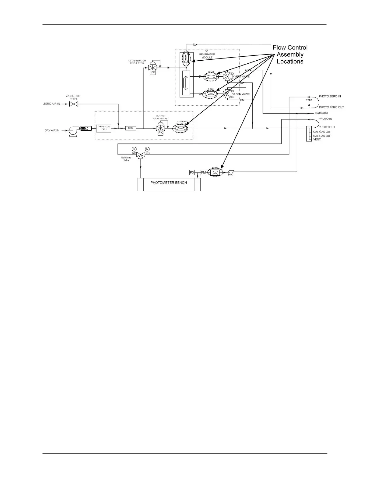
Figure 9-2: Location of Gas Flow Control Assemblies - T703U
Photometer Critical Flow Orifice 9.1.1.1.
Critical flow orifices are a remarkably simple way to regulate stable gas flow
rates. They operate without moving parts by taking advantage of the laws of fluid
dynamics. By restricting the flow of gas though the orifice, a pressure differential
is created. This pressure differential combined with the action of the calibrator‟s
pump draws the gas through the orifice.
As the pressure on the downstream side of the orifice (the pump side) continues
to drop, the speed that the gas flows though the orifice continues to rise. Once
the ratio of upstream pressure to downstream pressure is greater than 2:1, the
velocity of the gas through the orifice reaches the speed of sound. As long as that
ratio stays at least 2:1 the gas flow rate is unaffected by any fluctuations, surges,
or changes in downstream pressure because such variations only travel at the
speed of sound themselves and are therefore cancelled out by the sonic
shockwave at the downstream exit of the critical flow orifice.
The actual flow rate of gas through the orifice (volume of gas per unit of time),
depends on the size and shape of the aperture in the orifice. The larger the hole,
the more gas molecules, moving at the speed of sound, pass through the orifice.
INTERNAL GAS PRESSURE SENSORS 9.1.2.
There are two pressure sensors in the T703/T703U: one for the regulator and one
for the photometer. See Figure 3-5 (T703) or Figure 3-7 (T703U) for the location
of the Pressure/Flow Sensor.
A 100 psig pressure sensor on this PCA is used to monitor the downstream
regulator pressure. This value is displayed on the front panel as a test
measurement called REG PRESSURE.
A second pressure located on the rear PCA measures the pressure of gas in the
photometer‟s absorption tube. This sensor is a 0-15 psia (absolute pressure)


 To Next Page