EasyManua.ls Logo

TELEDYNE API T703U - Figure 3-11: Digital Control Input Connectors

Default Icon
273 pages
Print Icon
To Next Page IconTo Next Page
To Previous Page IconTo Previous Page
Loading...
Teledyne API T703/T703U Calibrator Operation Manual Getting Started
31
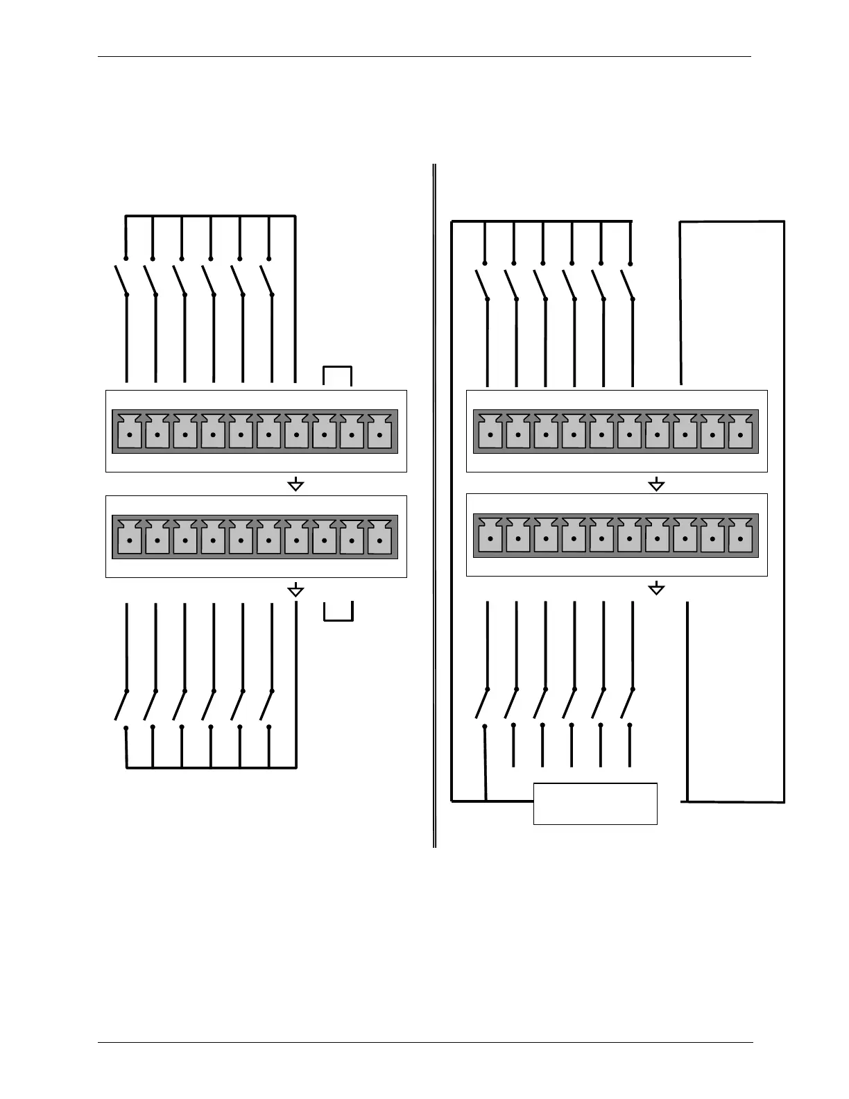
There are two methods for energizing the control inputs. The internal +5V
available from the pin labeled ā€œ+ā€ is the most convenient method. However, if
full isolation is required, an external 5 VDC power supply should be used.
Example of Local Power Connections
Example of External Power Connections
-
7 8 9 10 11 12 U +
CONTROL Bit-07
CONTROL Bit-08
CONTROL Bit-09
CONTROL Bit-10
CONTROL Bit-11
CONTROL Bit-12
+
5 VDC Power
Supply
7 8 9 10 11 12 U +
CONTROL Bit-07
CONTROL Bit-08
CONTROL Bit-09
CONTROL Bit-10
CONTROL Bit-11
1 2 3 4 5 6 U +
CONTROL Bit-01
CONTROL Bit-02
CONTROL Bit-03
CONTROL Bit-04
CONTROL Bit-05
1 2 3 4 5 6 U +
CONTROL Bit-01
CONTROL Bit-02
CONTROL Bit-03
CONTROL Bit-05
CONTROL Bit-06
CONTROL Bit-06
CONTROL Bit-04
CONTROL Bit-12
Figure 3-11: Digital Control Input Connectors
07223D DCN7107

Table of Contents