Additional adjustment can be made by physically
rotating the lamp in it‟s housing.
To do this, slightly loosen the UV lamp
setscrew.
Next, slowly rotate the lamp up to ¼ turn in
either direction while watching the
PHOTO_DET signal.
Once the optimum lamp position is
determined, re-tighten the lamp
setscrew
Using an insulated pot adjustment tool, Turn the UV
DETECTOR GAIN ADJUSTMENT POT until the value of
PHOTO_DET is as close as possible to 4600.0 MV.
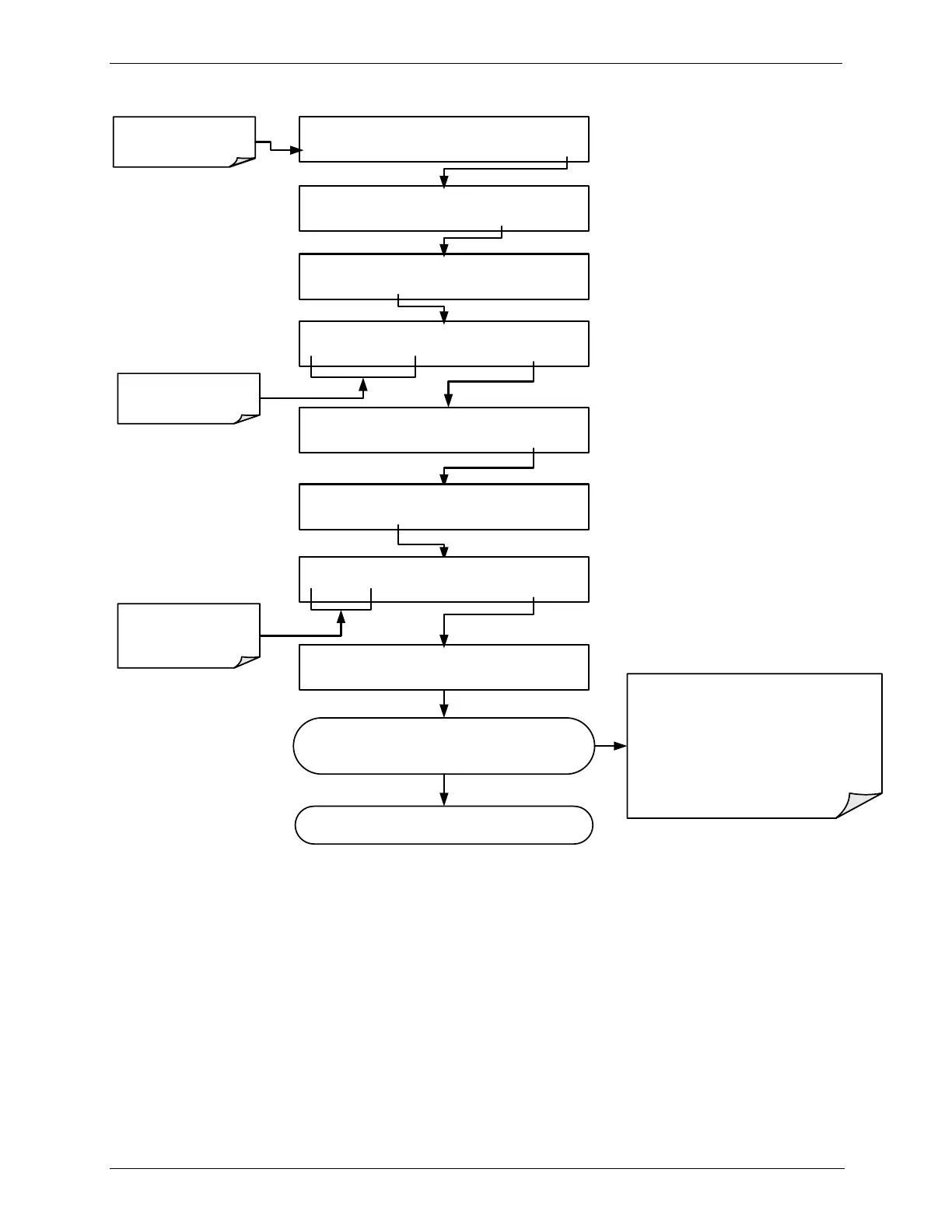
STANDBY ACT =STANDBY
<TST TST> GEN STBY SEQ SETUP
Make sure that the
instrument is in Standby
mode.
SETUP X.X PRIMARY SETUP MENU
O3 SEQ CFG CLK PASS MORE EXIT
SETUP X.X SECONDARY SETUP MENU
COMM VARS DIAG EXIT
SETUP X.X ENTER PASSWORD
8 1 8 ENTR EXIT
Toggle these buttons to
enter the correct
PASSWORD
DIAG SIGNAL I/O
PREV NEXT ENTR EXIT
DIAG I/O 1) CONTROL_IN_2=OFF
PREV NEXT JUMP PRNT EXIT
DIAG 17) PHOTO_DET = 3342.2 MV
PREV NEXT PRNT EXIT
DIAG I/O JUMP TO:1
1 7 ENTR EXIT
Toggle these buttons to
show the ID number for
the desired signal
(see Appendix A)
If a minimum reading of 3500.0 mV can not be reached,
the lamp must be replaced.
6. Replace the cover on the instrument.