TH2829X Series Operation Manual Chapter 7 Transformer Auto Scanning Test
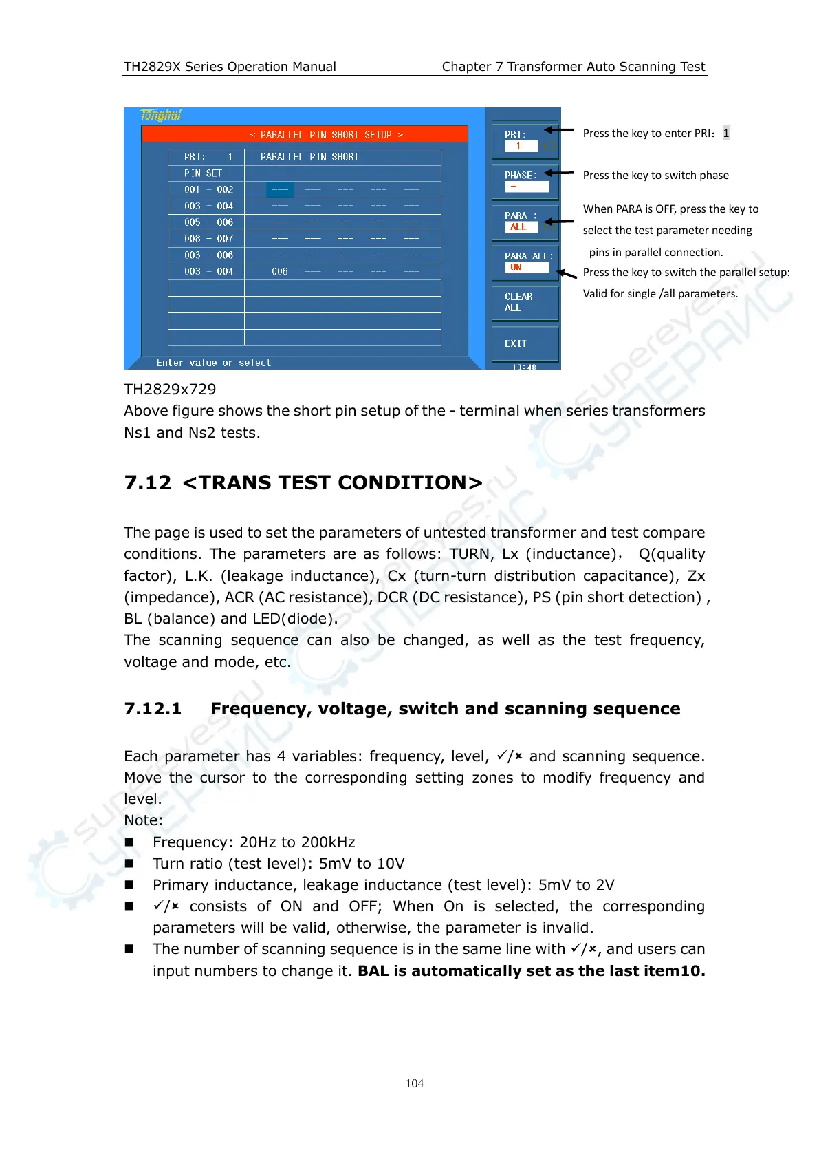
TH2829x729
Above figure shows the short pin setup of the - terminal when series transformers
Ns1 and Ns2 tests.
7.12 <TRANS TEST CONDITION>
The page is used to set the parameters of untested transformer and test compare
conditions. The parameters are as follows: TURN, Lx (inductance)
, Q(quality
factor), L.K. (leakage inductance), Cx (turn-turn distribution capacitance), Zx
(impedance), ACR (AC resistance), DCR (DC resistance), PS (pin short detection) ,
BL (balance) and LED(diode).
The scanning sequence can also be changed, as well as the test frequency,
voltage and mode, etc.
7.12.1 Frequency, voltage, switch and scanning sequence
Each parameter has 4 variables: frequency, level, / and scanning sequence.
Move the cursor to the corresponding setting zones to modify frequency and
level.
Note:
Frequency: 20Hz to 200kHz
Turn ratio (test level): 5mV to 10V
Primary inductance, leakage inductance (test level): 5mV to 2V
/ consists of ON and OFF; When On is selected, the corresponding
parameters will be valid, otherwise, the parameter is invalid.
The number of scanning sequence is in the same line with /, and users can
input numbers to change it. BAL is automatically set as the last item10.
Press the key to enter PRI:1
Press the key to switch phase
When PARA is OFF, press the key to
select the test parameter needing
pins in parallel connection.
series connection
Press the key to switch the parallel setup:
Valid for single /all parameters.