TH2829X Series Operation Manual Chapter 7 Transformer Auto Scanning Test
54321
HANDLER
SCANNER
CYLINDER
TEST LINE
FOOT.C
+ -
N1N9VCC
GO NG S R GND
10) Control socket of air valve controller (electromagnetic valve): The switch for
controlling TH1901A and the cylinder. The power is DC24V. There is no such
a controller in TH1901B.
11) Fixture pin number. In above figure, 1~20 is the corresponding pin number.
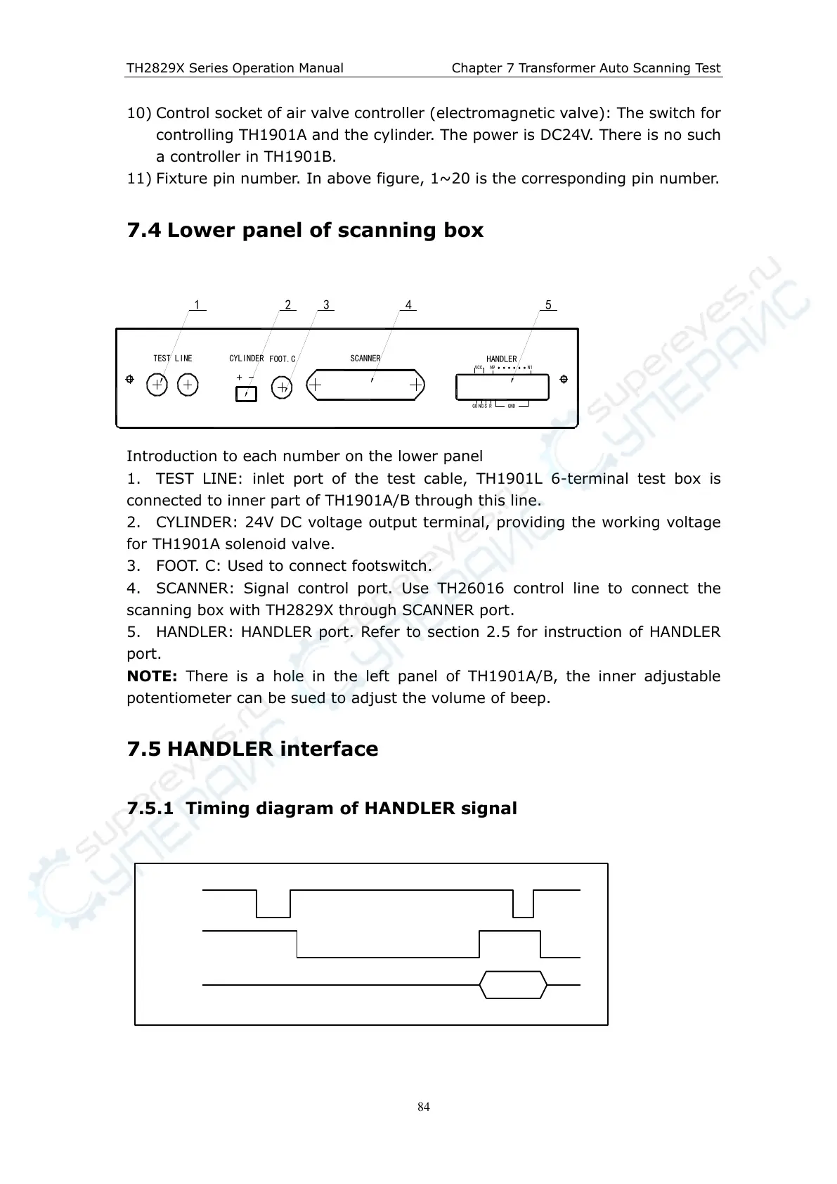
7.4 Lower panel of scanning box
Introduction to each number on the lower panel
1. TEST LINE: inlet port of the test cable, TH1901L 6-terminal test box is
connected to inner part of TH1901A/B through this line.
2. CYLINDER: 24V DC voltage output terminal, providing the working voltage
for TH1901A solenoid valve.
3. FOOT. C: Used to connect footswitch.
4. SCANNER: Signal control port. Use TH26016 control line to connect the
scanning box with TH2829X through SCANNER port.
5. HANDLER: HANDLER port. Refer to section 2.5 for instruction of HANDLER
port.
NOTE: There is a hole in the left panel of TH1901A/B, the inner adjustable
potentiometer can be sued to adjust the volume of beep.
7.5 HANDLER interface
7.5.1 Timing diagram of HANDLER signal