TH2829X Series Operation Manual Chapter 7 Transformer Auto Scanning Test
VOLT = Primary test voltage * secondary voltage / primary voltage
Vs:Vp = Secondary voltage/ primary voltage
Ns:Np = Secondary turn/ primary turn
TURN_L= Inductance ratio mode
Np:Ns = Primary turn/ secondary turn
Lp:Ls = Primary inductance/ secondary inductance
It is recommended to put the windings with multi-turns in the primary turn ratio,
the reasons are as follows:
1. By the influence of output internal resistance (10, 30, 50, 100), when the
primary inductance is small, the distributed voltage signal will also be small
and the energy the transformer gets is also weak. The test cable and the relay
will attenuate a part of energy, so the stability and accuracy will be affected.
2. If the primary signal is forced to be enlarged, then the voltage generated
by secondary multi-winding will be high and it may be over the range of the
instrument and thus further affect the test accuracy.
3. If the winding with multi-turns is put in primary test, then the energy of
the transformer will be strong and above 2 problems can be ignored.
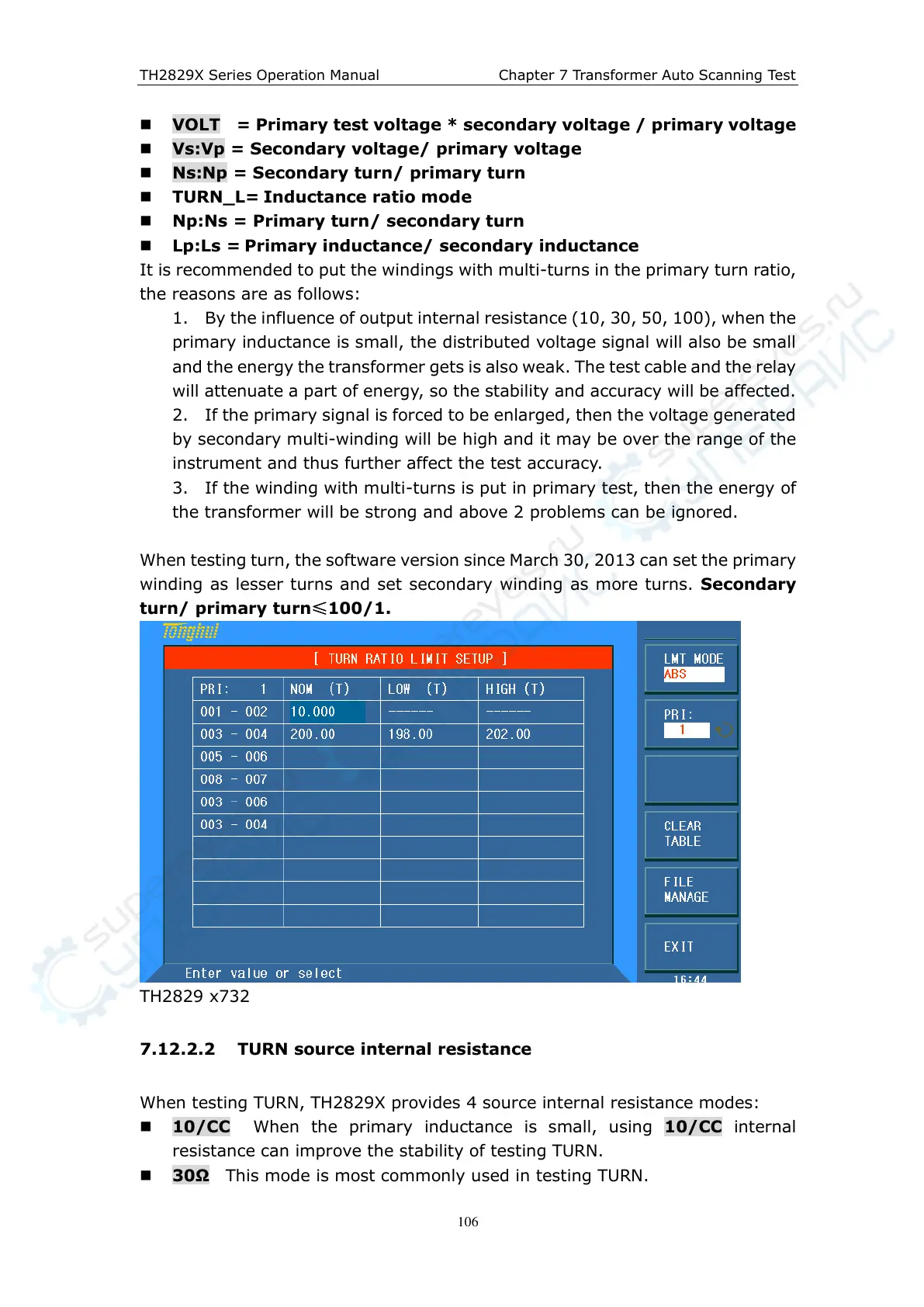
When testing turn, the software version since March 30, 2013 can set the primary
winding as lesser turns and set secondary winding as more turns. Secondary
turn/ primary turn
≤100/1.
TH2829 x732
7.12.2.2 TURN source internal resistance
When testing TURN, TH2829X provides 4 source internal resistance modes:
10/CC When the primary inductance is small, using 10/CC internal
resistance can improve the stability of testing TURN.
30Ω This mode is most commonly used in testing TURN.