TH2829X Series Operation Manual Chapter 10 HANDLER
NOTE:as the HANDLER interface card of this instrument, the internal
voltage adopts +5V. The actual using value of Internal Power Supply
Voltage described in this manual is +5V and it is no n -ajustable. When
using Internal Power Supply Voltage, the jumping line of Handler
interface board must be in short circuit.
Considering the anti-interference ability of TH2829, we suggest you to
provide and use external +5V power supply as pull-up power supply of
optocoupler. Now, the jumping line should be open (factory settings).
Possible jumping line:
1.Use internal power supply (+5V), set JP1 and JP3 as VCC, JP2 and JP4 in short
circuit.
2.Use the same external power supply(EXTV1, EXTV2: same), set JP1 and JP3 as
external power supply, JP2 and JP4 in short circuit.
3. Use two sets of external power supply (EXTV1, EXTV2: not same), set JP1 and
JP3 as external power supply, disconnect JP2 and JP4.
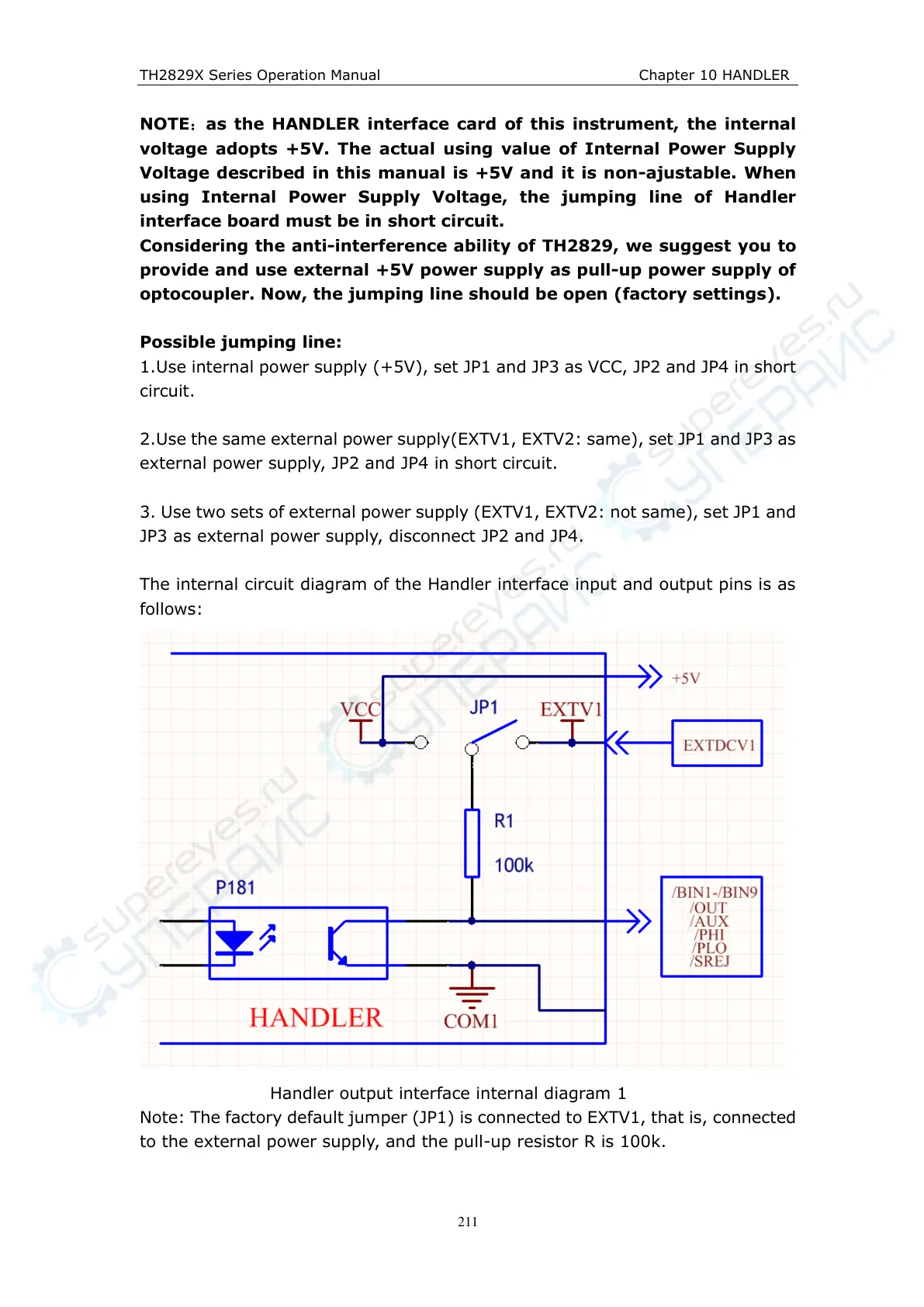
The internal circuit diagram of the Handler interface input and output pins is as
follows:
Handler output interface internal diagram 1
Note: The factory default jumper (JP1) is connected to EXTV1, that is, connected
to the external power supply, and the pull-up resistor R is 100k.