•Themainpowerrelaysuppliespowertothefuses(andallofthecircuits
protectedbythefuses)infuseblock2;refertoFuseIdenticationand
Function(page6–12).Themainpowerrelayisenergizedwhenthekey
switchisintheRUNorSTARTposition.
•Theglowplugrelaysuppliespowertotheengineglowplugs.Formodel
31900and31901machines;theglowplugrelayisenergizedwhiletheglow
switchispressed.Formodel31902and31903machines,theglowrelayis
energizedbytheYanmarengineECU.
•Thepullcoilrelaysuppliespowertothepullcoiloftheenginefuelsolenoid
(models31900and31901only).Thepullcoilrelayisenergizedbythestart
interlockrelayandthedelaytimer.
•Thecabpowerrelaysuppliespowertothecabcontrolcircuitsof
Groundsmaster3310machines.
•Thehornrelaysuppliespowertotheoptionalhorn.
TestingRelayswith4Terminals
RefertoFigure93forthisprocedure.
1.Parkthemachineonalevelsurface,lowerthecuttingunit(orattachment),
engagetheparkingbrake,setthekeyswitchtotheOFFpositionandremove
thekeyfromthekeyswitch.
2.Disconnectthegroundcableatthebattery;refertoRemovingandInstalling
theBattery(page6–64).
3.Removetheoperator’sconsolecovers;refertoRemovingandInstallingthe
Operator’sConsoleCovers(page7–23).
4.Locatetherelaythatistobetestedanddisconnectthewireharness
connectorsfromtherelay.Checktherelayandtheharnessconnectorfor
damageorcorrosionandcleanorrepairifnecessary.
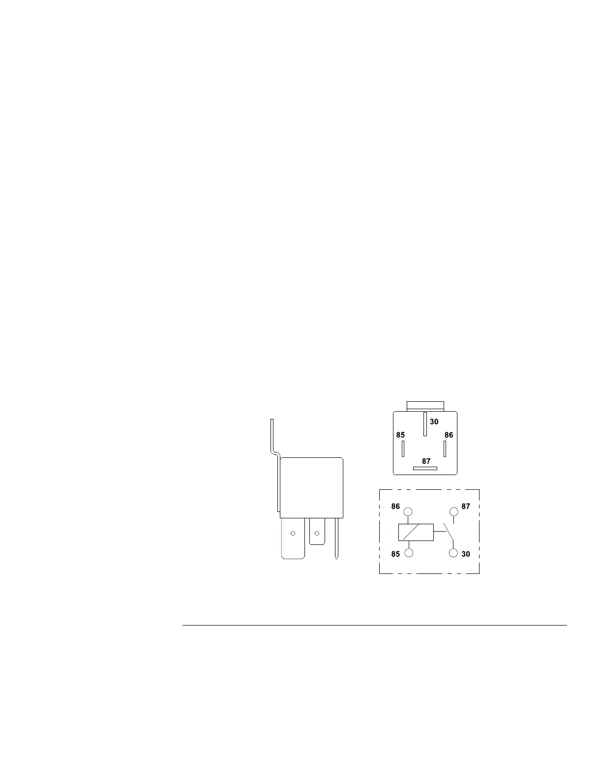
g256779
Figure95
Relaywith4terminals
Note:Priortotakingsmallresistancereadingswithadigitalmultimeter,short
themetertestleadstogether.Themeterwilldisplayasmallresistancevalue
(usually0.5ohmsorless).Thisresistanceisduetotheinternalresistanceof
themeterandtestleads.Subtractthisvaluefromthemeasuredvaluefor
thetestedcomponent.
5.Usingamultimeter(ohmssetting),measurecoilresistancebetween
terminals85and86.Resistanceshouldbebetween70and100ohms.
Groundsmaster
®
3200,3300and3310
Page6–43
ElectricalSystem:TestingtheElectricalComponents
19240SLRevA
 Loading...


