ENGINE
4-141TX525 Service Manual Rev. 000
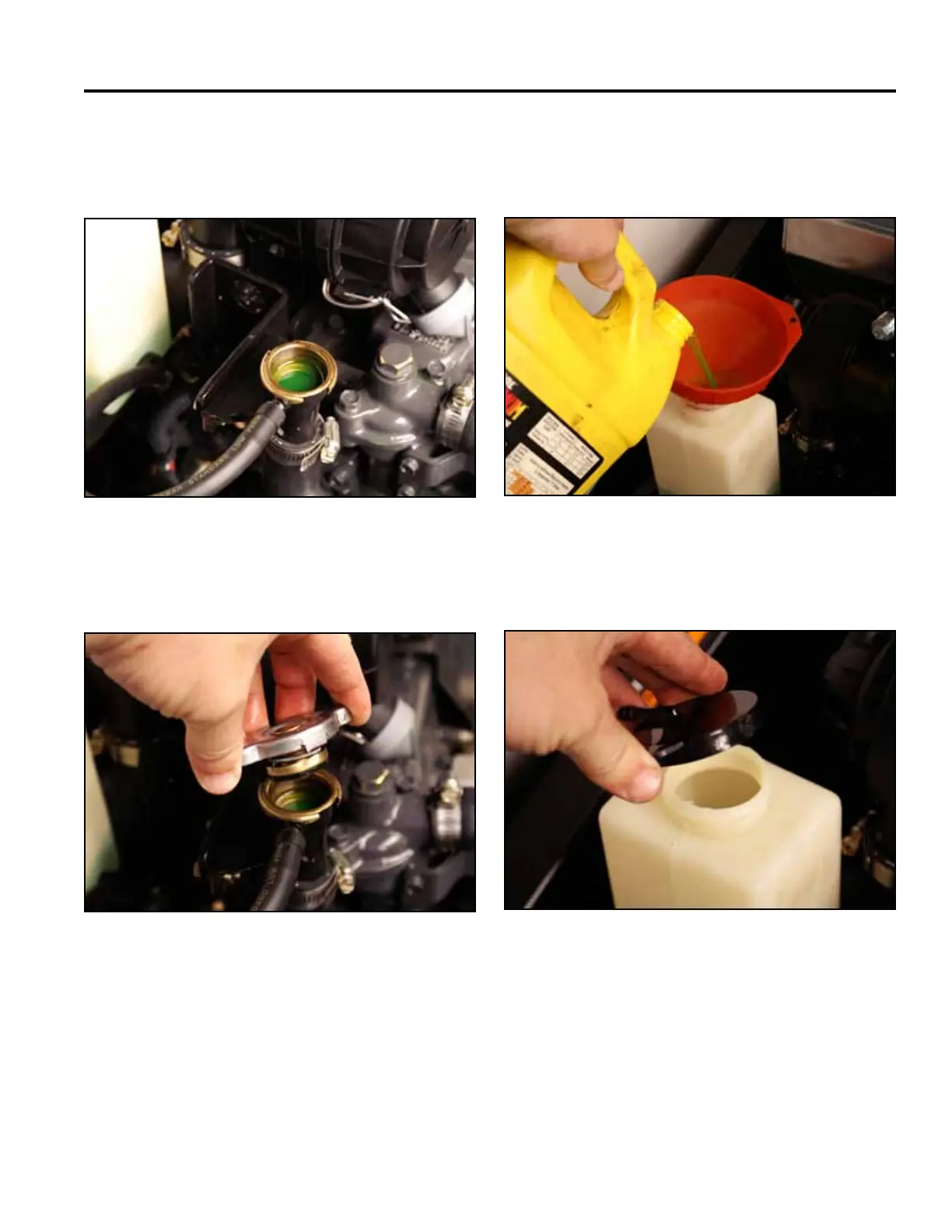
8. Pourcoolantmixtureintothecoolantllerneckuntil
thecoolantlevelcomesintothellerneck(Fig.
0613).
Fig 0613 Coolant 007
9. Installthecoolantllcap(Fig.0614).
Fig 0614 Coolant 002
10. Removetheexpansiontankcapandaddcoolant
mixtureintotheexpansiontankuntilitreachesthe
fulllineonthesideofthetank(Fig.0615).
Fig 0615 Coolant 009
11. Installtheexpansiontankcap(Fig.0616).
Fig 0616 Coolant 008