BRAKES
8-7TX525 Service Manual Rev. 000
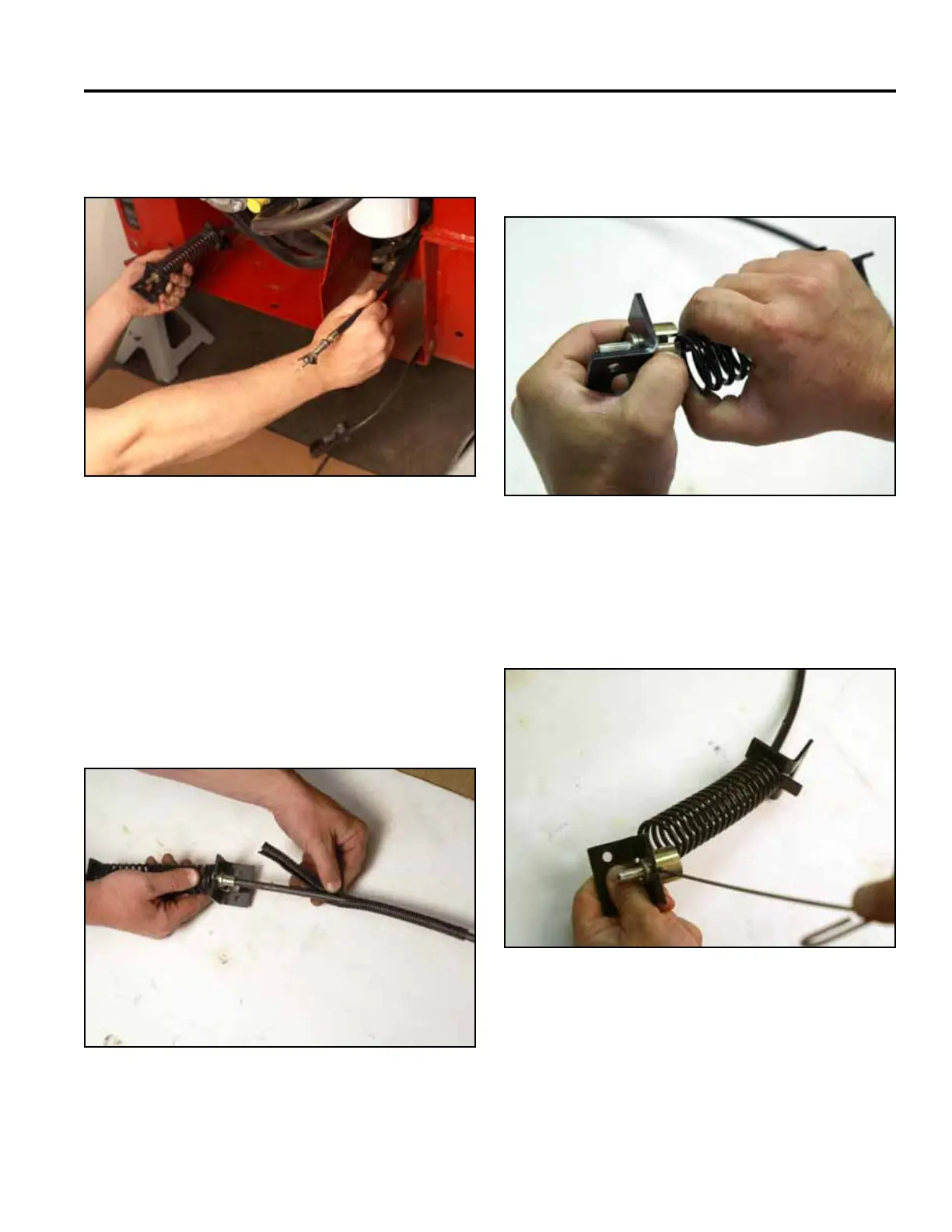
27. Route the brake cable out of the frame and remove
the brake assembly from the machine (Fig. 1658).
Fig 1658 PICT-4328
Brake Cable Replacement 270000100 -
270000999
1. Remove the brake assembly from the frame.
Refer to “Brake Assembly Removal 270000100 -
270000999” on page 8-1.
2. Remove the convoluted tube from the brake cable
(Fig. 1659).
Fig 1659 PICT-4299a
3. Slide the spring back to expose the tube guide and
set screw. Hold the spring back by placing the spring
in the slot on the tube guide (Fig. 1660).
Fig 1660 PICT-1697a
4. Using a 3/32” hex wrench, loosen the set screw that
secures the tube guide to the brake cable assembly
(Fig. 1661).
Fig 1661 PICT-1699a