HYDRAULIC SYSTEM
6-44 Rev. 000 TX525 Service Manual
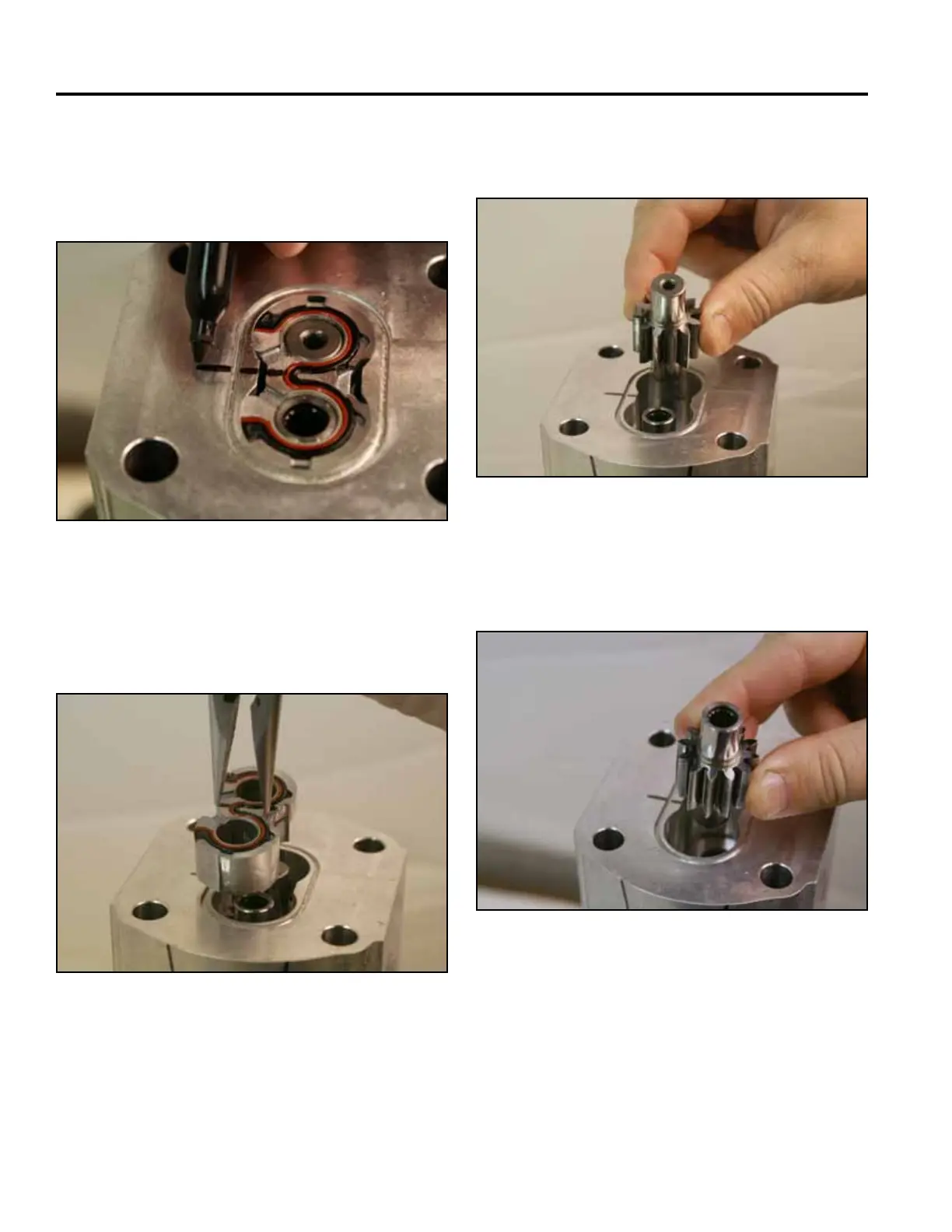
1. Mark the bushing assembly with a single line that
extends out onto the pump housing (Fig. 0994).
3. Remove the driven gear from the pump assembly
(Fig. 0996).
Fig 0994 PICT-2829
Fig 0996 PICT-2832a
4. Remove the drive gear from the pump assembly
(Fig. 0997).
2. Using a needle nose pliers, grab the center of the
small bushing and lift the bushing from the pump
housing assembly (Fig. 0995).
Fig 0997 PICT-2833a
Fig 0995 PICT-2830a
6 gpm Pump Disassembly