DRIVE SYSTEM
7-48 Rev. 000 TX525 Service Manual
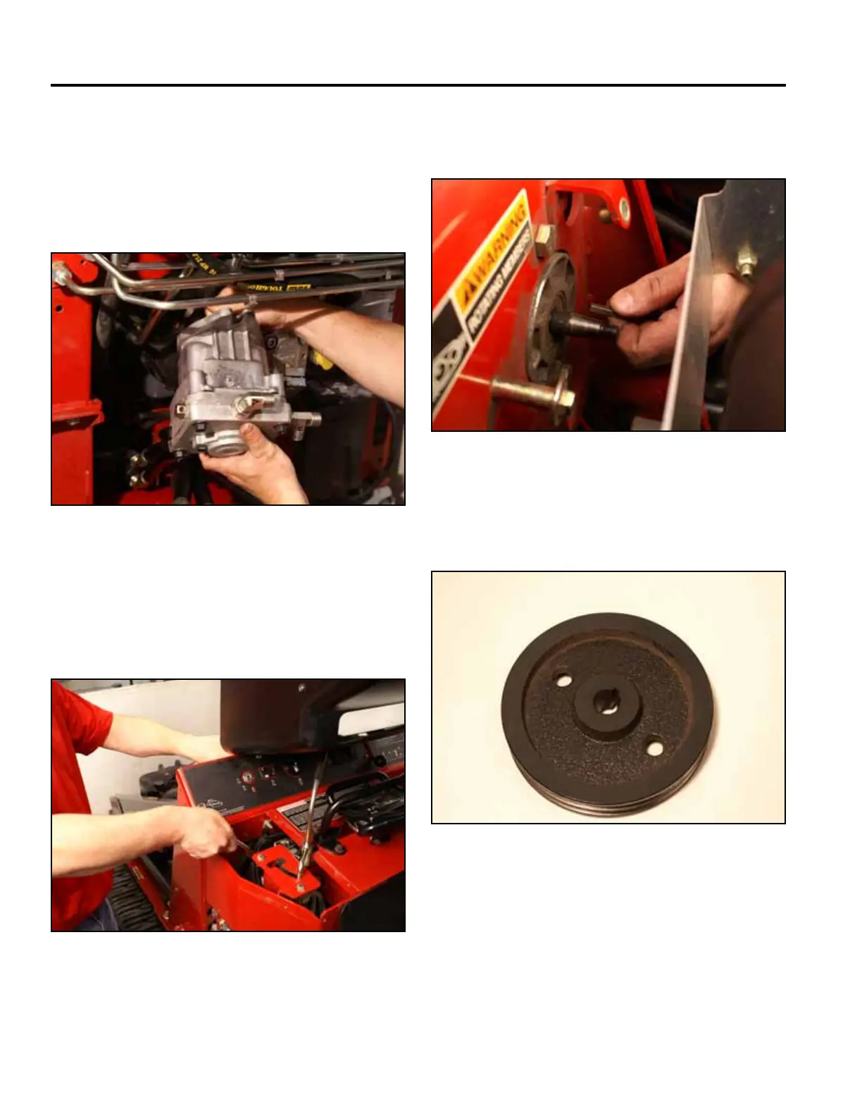
Left Hydrostatic Pump Installation
Fig 1443 PICT-4627
2. Using a 3/4” socket and wrench, install the top bolt
and nut. Tighten the lower bolt and nut securing the
left hand hydrostatic pump to the tower frame (Fig.
1444).
Fig 1444 PICT-4619
1. With the lower bolt and nut loosely installed in the
tower frame, position the left hand hydrostatic pump
so the pump shaft is inserted through the frame (Fig.
1443).
3. Install a key into the hydrostatic pump shaft keyway
(Fig. 1445).
Fig 1445 PICT-4598
4. The pulley has a tapered through hole and a thicker
angeononeside(Fig.1446).
Fig 1446 PICT-4659