ELECTRICAL
5-18 Rev. 000 TX525 Service Manual
How It Works
Testing
The alternator is belt driven from the engine crankshaft
pulley. The alternator generates AC (alternating current)
using a rotor made up of north and south pole magnets
staggered around the eld windings that spins inside of
the stator. When the rotor spins it creates a magnetic
eld that induces voltage into the stator. Brushes and
slip rings on each end of the rotor shaft conduct current
to the rotor eld windings. The diode (rectier) converts
the AC power to DC (direct current). A solid state voltage
regulator (internal to the alternator) determines how
much charging current is needed by the battery.
1. Clean and inspect both battery terminals and cables.
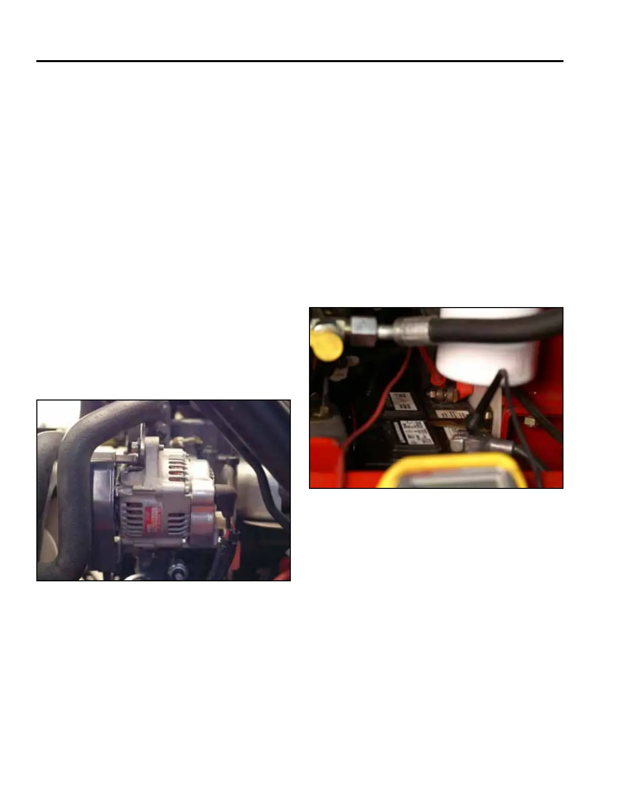
Using a voltmeter set to DC power:
2. Touch the red voltmeter lead to the positive battery
terminal.
3. Touch the black voltmeter lead to the ground.
4. Start the engine at 1/2 throttle.
• The voltage should read 13.8 volts to 14.8 volts.
5. Place a load onto the electrical system.
• The voltage should read around 13.8 volts to
14.8 volts.
• A reading of 12 volts or less would indicate the
alternator is not working to specication.
Fig 0830 PICT-8769
The alternator charges the battery to operate the
electrical components and accessories.
Batteries in equipment stored for some portion of the
year will self-discharge. Sulfation between the battery
plates can occur and shorten the life of the battery. It
is important to periodically charge the battery during
storage to prevent damage due to sulfation.
Alternator
Purpose
Location
The alternator is located on the front left side of the
engine (Fig. 0829).
Fig 0829 PICT-5620a
Storage