DRIVE SYSTEM
7-77TX525 Service Manual Rev. 000
4. Remove the hydraulic jack and board.
5. Raise the loader arm approximately 12” (30cm).
Secure the loader arms.
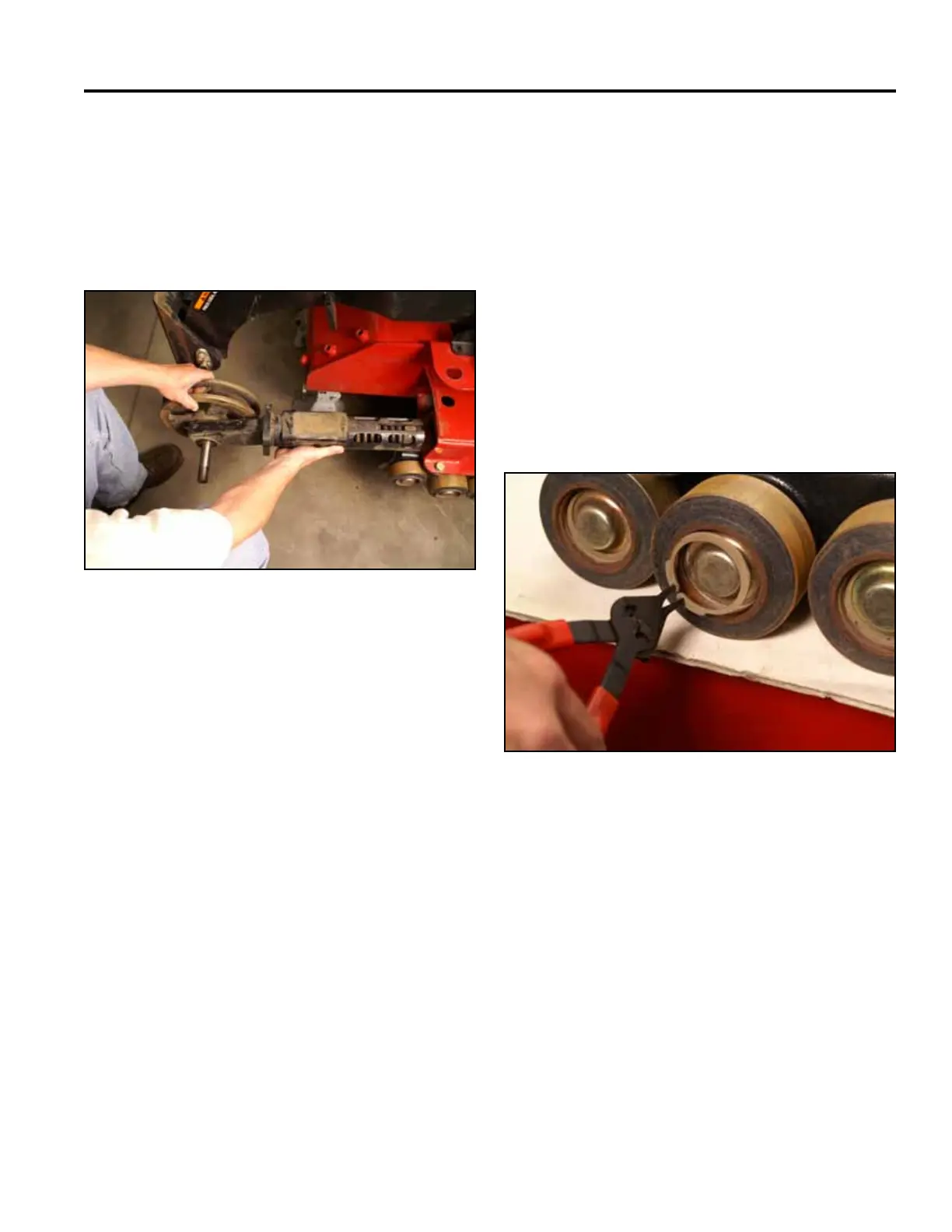
6. Slide the tensioner arm into the mainframe (Fig.
1549).
Fig 1549 PICT-4520
7. Align the track guide. Refer to “Track Guide
Alignment” on page 7-3.
8. Install the track. Refer to “Wide Track Installation”
on page 7-70, or “Narrow Track Installation” on page
7-73.
Road Wheel Replacement
Road Wheel Removal
1. Remove the snap ring securing the wheel bearing
cap to the road wheel (Fig. 1550).
Fig 1550 PICT-4524
For inner road wheel replacement: To replace the inner
road wheels, the track guide assembly must be removed
from the machine. Refer to “Track Guide Removal” on
page 7-75.
For this procedure, the track guide has been removed
from the machine for photo purposes.