HYDRAULIC SYSTEM
6-94 Rev. 000 TX525 Service Manual
Lift Cylinder Assembly Rebuild
1. Extend the ram of the tilt cylinder out approximately
6” to 12” (15.24 to 30.48cm).
2. Clean all dirt and other foreign substance from the
openings, particularly at the head of the hydraulic
cylinder.
3. Clamp the tilt cylinder in a vise so that the locking
ring slot is facing up.
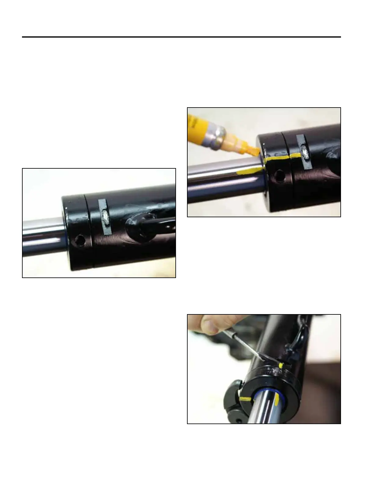
4. Clean out all material from the locking slot (Fig.
1191).
Note: If excessive wear due to side-loads or binding
is a possibility, mark or note the piston and
head relationship to the rod and tube. This
condition will usually show up as a highly
polished surface on the piston and head 90°
to the pin rotation axis (Fig. 1192).
Fig 1191 PICT-3034
Fig 1192 PICT-3035
5. Using a spanner wrench installed in the holes
provided, rotate the head counterclockwise until
the edge of the retaining ring appears in the milled
opening of the tube. Insert a at blade screwdriver
between the beveled edge of the retaining ring and
the cylinder barrel to start the retaining ring through
the opening (Fig. 1193).
Fig 1193 PICT-3036