HYDRAULIC TESTING
9-7TX525 Service Manual Rev. 000
8. Start the engine and run at full rpm.
9. Activate the auxiliary valve handle and hold. View
the ow (gpm) gauge, take reading.
10. Flow specication is 14 gpm (53 lpm).
11. Lower engine rpm.
12. Shut the engine off.
This test checks the system ow of the auxiliary circuit.
The components involved in this test are: gear pump,
auxiliary valve, auxiliary couplers and hoses. When the
traction unit tests to the recommendation the attachment
may be at fault.
Auxiliary Circuit Flow Test
1. Cycle the hydraulic oil until warm.
2. Park the unit on level ground.
3. Set the park brake.
4. Shut the engine off.
5. Cycle the auxiliary valve to relieve any pressure from
the circuit.
6. Wipe the couplers clean.
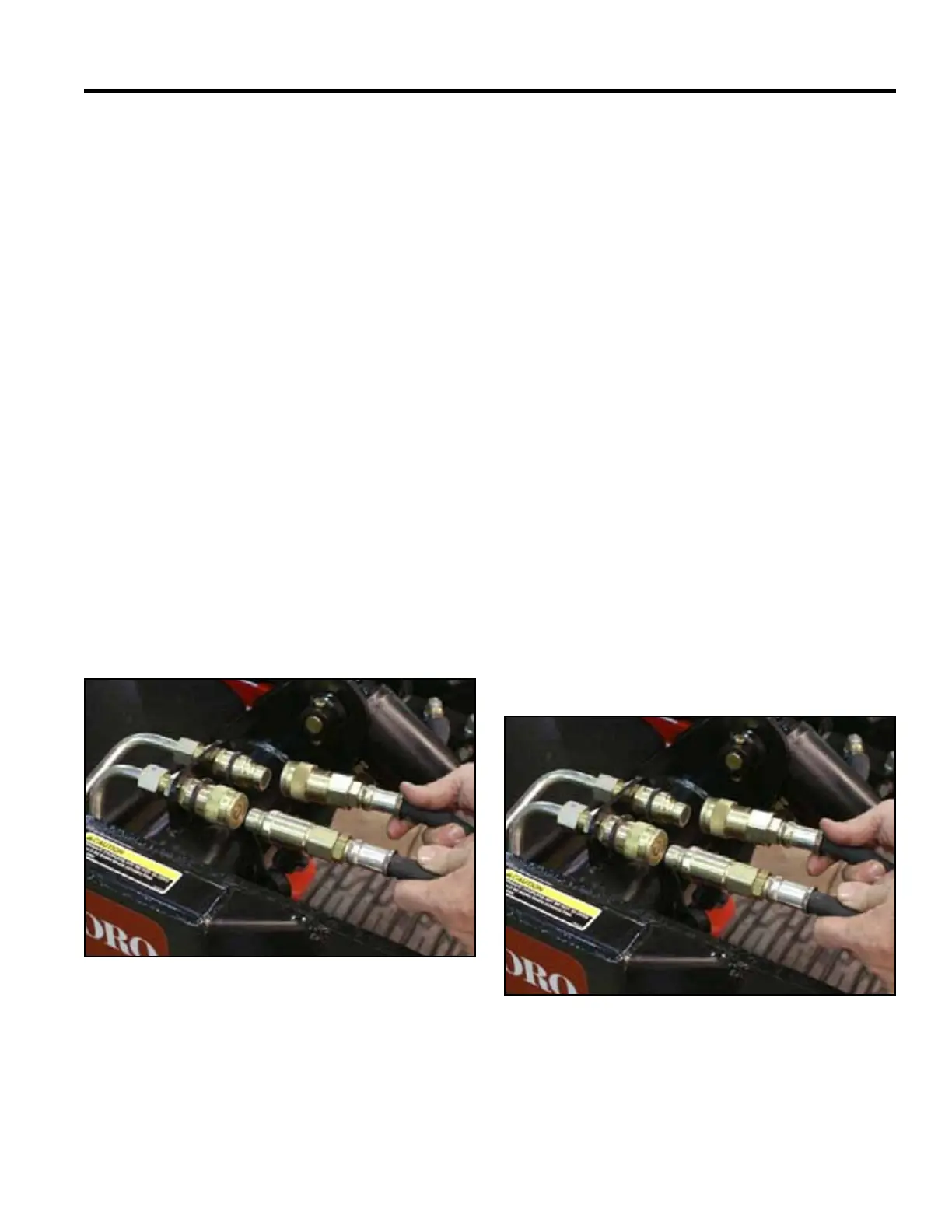
7. Plug the ow meter couplers into the TX couplers
(Fig. 1850).
Fig 1850 PICT-3400a
Auxiliary Flow Testing
If the gpm does not meet the specication then replace
the hydraulic pump.
4. Release the park brake.
Troubleshooting
1. Let the engine and hydraulic oil cool.
2. Cycle the auxiliary valve to relieve any pressure in
the circuit.
3. Push back on the female coupler locking collars to
separate ttings (Fig. 1851).
Fig 1851 PICT-3400a
Flow Meter Removal