BRAKES
8-32 Rev. 000 TX525 Service Manual
Brake Plate Removal
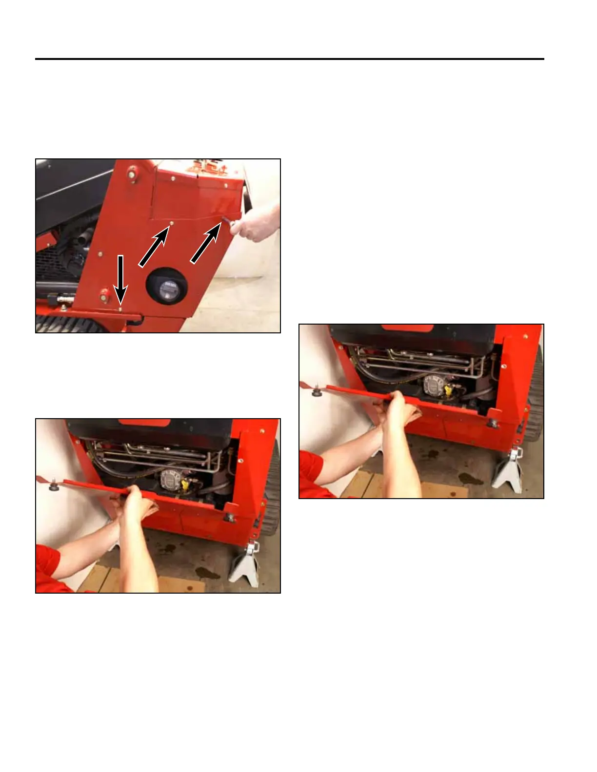
22. Install the rear access panel (Fig. 1753).
Fig 1753 PICT-4505
23. Lower the machine.
21. Position the left hand rear cover support panel to
the tower. Using a 3/8” socket, install 3 screws to
secure the left rear cover support panel to the tower
assembly. Repeat to install right hand rear cover
support panel (Fig. 1752).
Fig 1752 PICT-4256
Brake Plate Replacement 280000100
& higher
The following procedures show removal and installation
of the left hand brake plate assembly. The procedure is
the same for removal and install of the right hand brake
plate assembly.
1. Raise the machine and set it on jack stands. Refer to
“Lifting the Machine for Service” on page 7-1.
2. Place the brake handle in the “OFF” position.
3. Remove the rear access panel (Fig. 1754).
Fig 1754 PICT-4505