BRAKES
8-33TX525 Service Manual Rev. 000
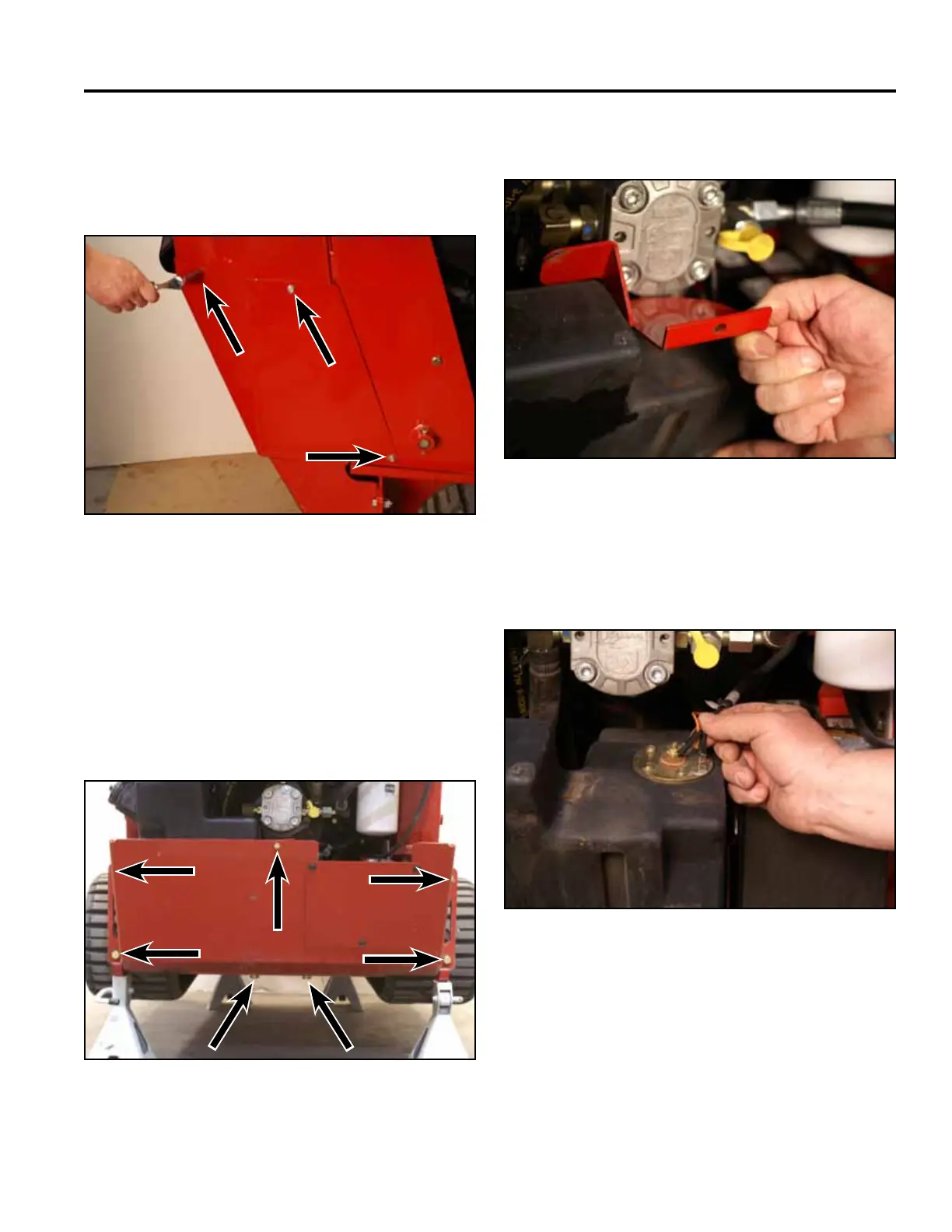
4. Using a 3/8” socket, remove the 6 screws that
secure the left and right rear cover support panels to
the tower assembly (3 screws per panel). Remove
the panels (Fig. 1755).
Fig 1755 PICT-4504
5. Using 3/4” and 1/2” sockets, remove the 7 bolts and
nuts securing the rear frame cover to the frame and
fuel tank bracket. Remove the rear frame cover (Fig.
1756).
Note: The rear of the machine may have to be lifted
to reposition the jack stands so that the rear
frame cover can be removed.
Fig 1756 PICT-4259
6. Remove the fuel tank bracket (Fig. 1757).
Fig 1757 PICT-5626
7. Disconnect the two wires (black and orange) from
the fuel sending unit located on the top of the fuel
tank (Fig. 1758).
Fig 1758 PICT-4262