ELECTRICAL
5-4 Rev. 000 TX525 Service Manual
Testing
How It Works
1. Check the 10 amp fuse.
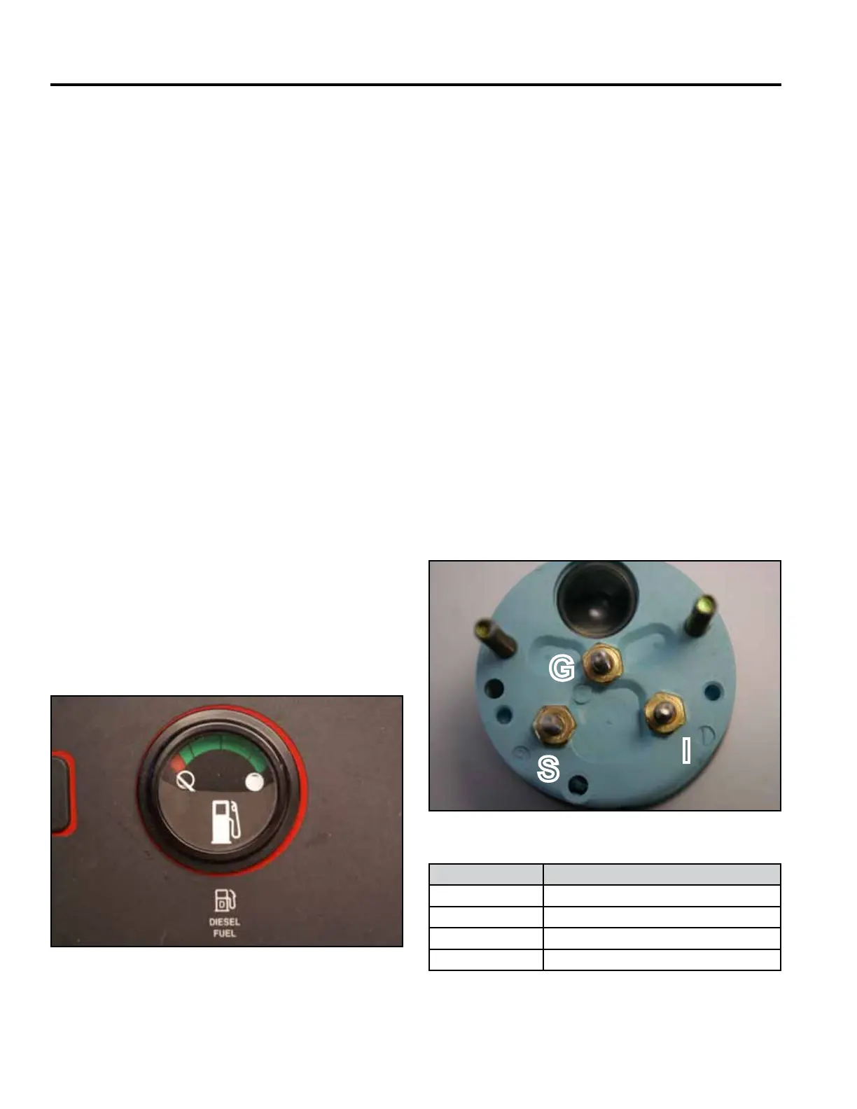
2. With the gauge still connected to the harness, turn
the key to the ON position.
3. Using a VOM, set scale capable of reading 12 volts
DC. Connect the negative lead to the ground term-
inal (G) and the other lead to the positive terminal
(S) (Fig. 0804) to verify the conditions in the table
below.
4. Replace the gauge if the fuel sender tests correctly
but voltage/fuel level indication does not.
Fig 0804 IMG-6971
Terminal Reading
G 0 Volts - Ground
I 12 Volts (B+ from Ignition switch)
S 2.5 Volts tank full*
S 7.5 Volts tank empty*
*All voltage readings should be within 20%. (Typical values)
How It Works
Testing
The digital hour meter is an electrical clock. It is not
repairable and can not be reset.
Location
Fuel Gauge
Purpose
The fuel gauge indicates the fuel level in the fuel tank.
The fuel gauge is located in the center of the control
panel (Fig. 0803).
Fig 0803 PICT-5274
The meter moves in proportion to the amount of resist-
ance provided by the fuel sender located in the fuel
tank. The movement is dampened to compensate for
movement of the fuel inside the tank.
The digital hour meter should be replaced if any of the
functions do not work properly. Prior to replacing the
hour meter, check the continuity of the signal wire, using
a VOM multi-meter (ohm setting) connected between the
ground wire, the pink wire at the battery charge indicator
and the hour meter. If there is continuity, replace the
hour meter.
S
G
I