HYDRAULIC SYSTEM
6-77TX525 Service Manual Rev. 000
10. Position the rubber bellows over the base plate
and install the tie strap in the groove of the rubber
bellows (Fig. 1123).
Note: When installing the rubber bellows, there
is an offset in the bellows. Ensure proper
installation.
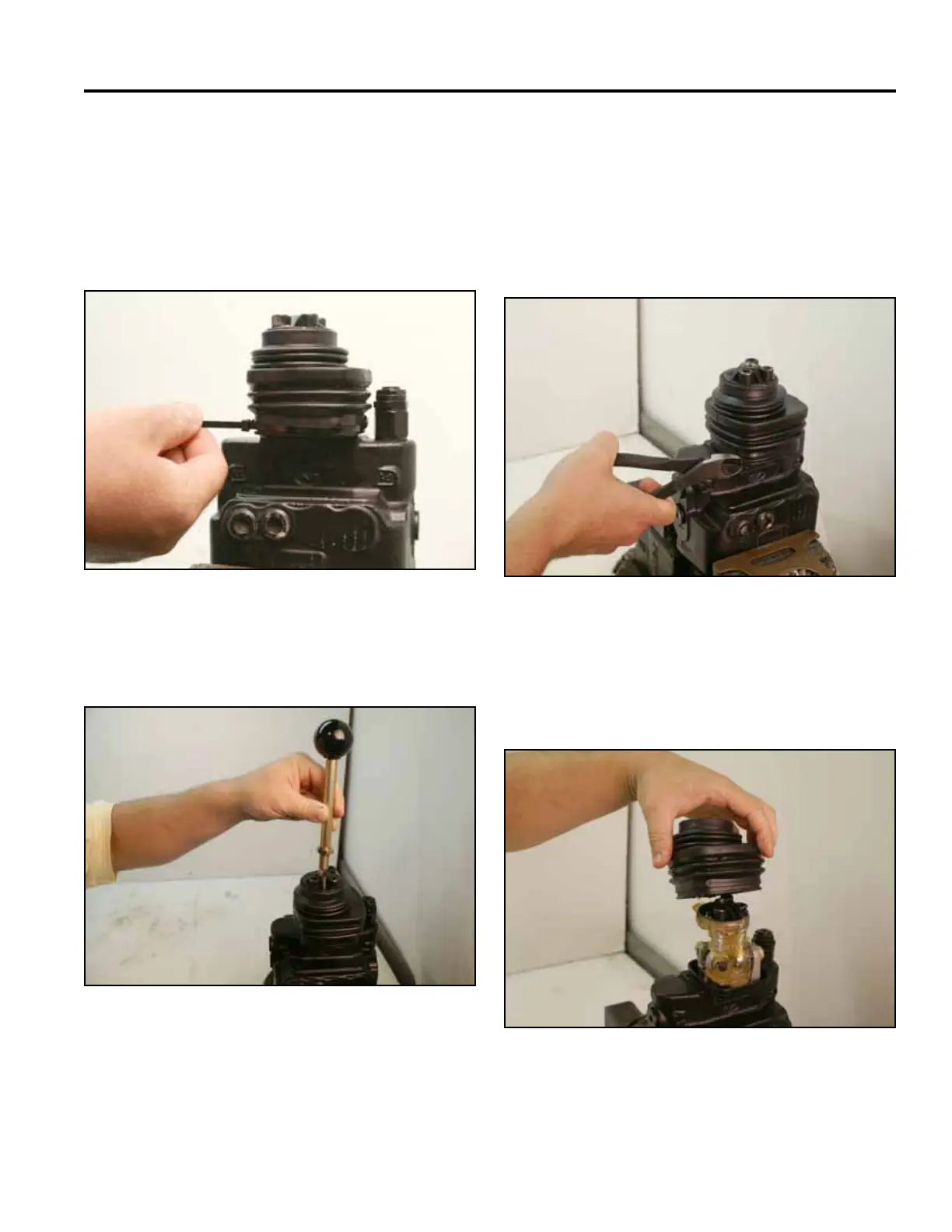
Note: To disassemble and assemble the valve, it is
best to hold the valve in a bench vise.
1. Remove the cable tie from around the rubber
bellows (Fig. 1125).
Fig 1123 PICT-2605a
Fig 1125 PICT-2588a
2. Remove the rubber bellows from the valve assembly
(Fig. 1126). Wipe the excess grease from the
joystick.
11. Install the lift/tilt handle (Fig. 1124).
Fig 1126 PICT-2589a
Fig 1124 PICT-2584a
Spool Removal