BRAKES
8-26 Rev. 000 TX525 Service Manual
Brake Assembly Installation 280000100 &
higher
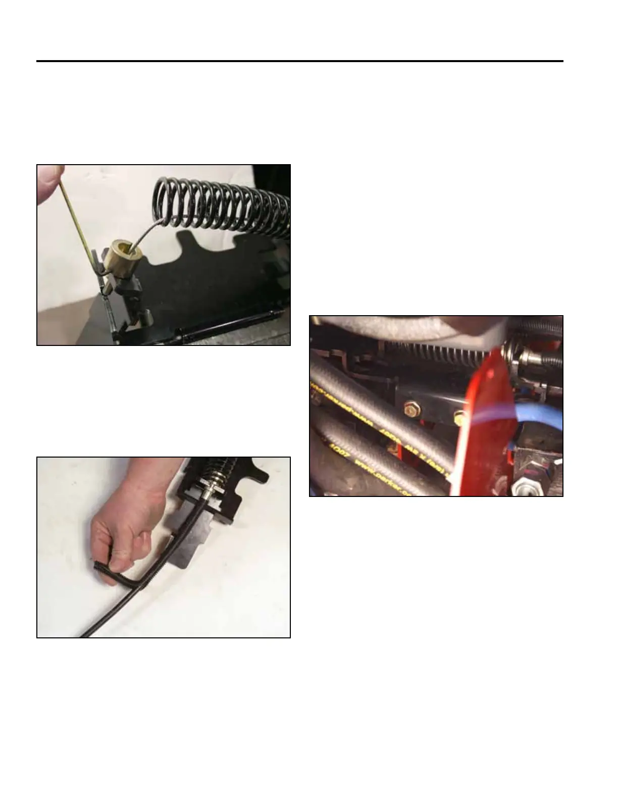
8. Place the cable end into the opening in the left hand
brake mounting bracket. Pull back on the spring
enough to allow the tube guide to be installed. Install
the tube guide onto the cable end and tighten the set
screw with 3/32” Allen wrench (Fig. 1730).
1. Route the brake cable into the machine as follows:
a. under the positive and negative battery cables
b. along the right side of the tower frame
(eventually will be located between the battery
guard and the tower frame)
c. up through the hydraulic lines and into the
control panel
2. Position brake assembly onto the frame bracket.
Using a 1/2” socket, install 2 bolts to secure the
brake bar support to the frame (Fig. 1732).
10. Install the brake assembly. Refer to “Brake As-
sembly Installation”, following.
Fig 1730 IMG_7508a
Fig 1732 PICT-4371
9. Apply the convoluted tube to the brake cable. Butt
the end of the convoluted tube up to the brake cable
collar (Fig. 1731).
Fig 1731 PICT-4376a