HYDRAULIC SYSTEM
6-57TX525 Service Manual Rev. 000
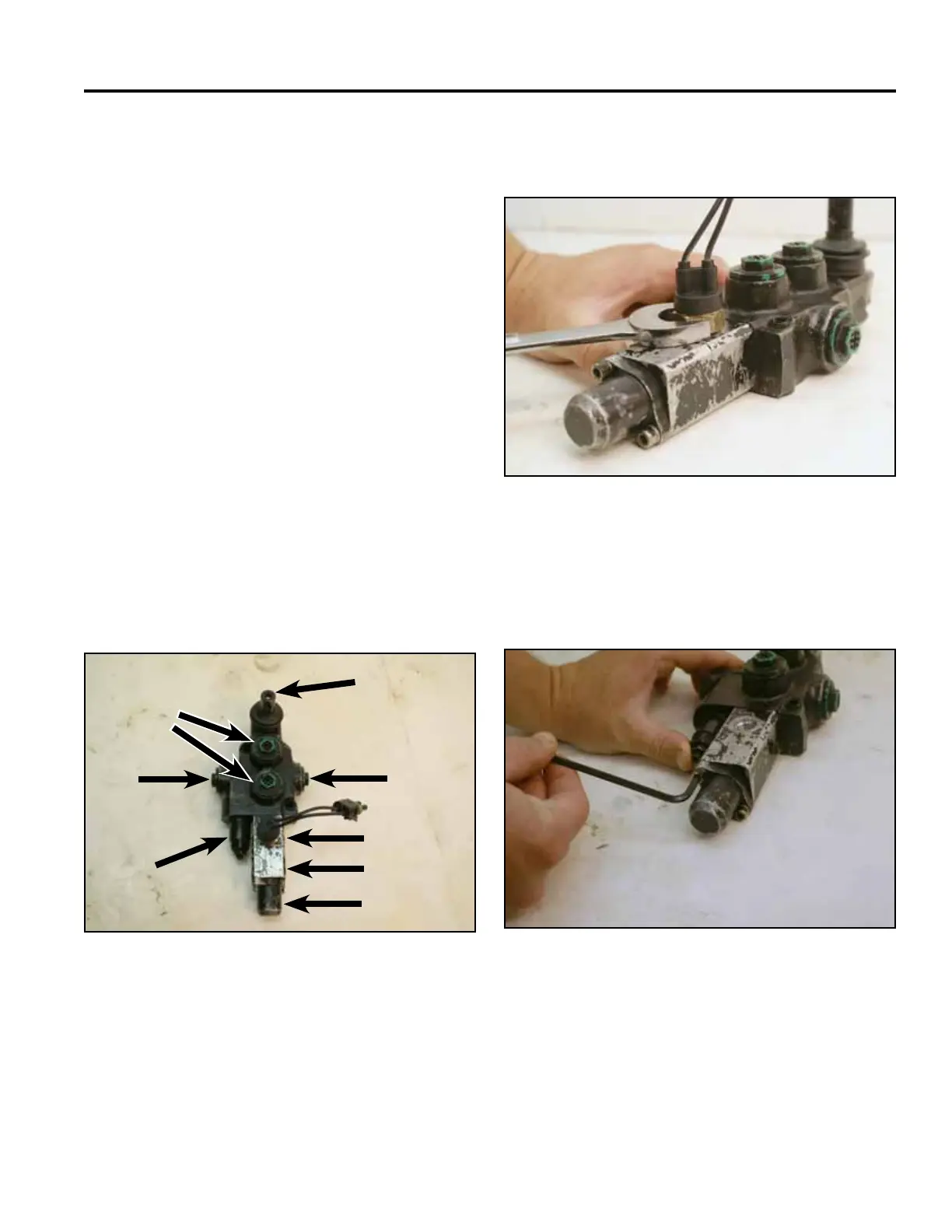
1. Using a 7/8” wrench, remove the safety switch from
the valve (Fig. 1046).
Fig 1046 PICT-2677a
2. Using a 4mm Allen wrench, loosen the two screws
securing the return spring cap to the valve (Fig.
1047).
Fig 1047 PICT-2678a
Auxiliary Valve Rebuild
Note: Cleanliness is a key factor in a successful
repair of any valve system. Thoroughly clean
all exposed surfaces prior to any type of
maintenance. Cleaning all parts by using
a solvent wash and air drying is usually
adequate. As with any precision equipment,
all parts must be kept free of foreign material
and chemicals. Protect all exposed sealing
areas and open cavities from damage and
foreign material.
Upon removal, all seals, o-rings, and gaskets
should be replaced. During installation, lightly
lubricate all seals, o-rings, and gaskets with
clean petroleum jelly prior to assembly.
Protect the inner diameter of seals and
o-rings from damage during assembly by
covering the shaft machined features with
plastic wrap or equivalent.
Auxiliary Valve
Fig 1045 PICT-2674a
A. Operator lever E. Return spring cap
B. Inlet F. Relief
C. Safety switch port G. Return
D. Detent cap H. Directional ports
A
B
C
D
E
F
G
H