DRIVE SYSTEM
7-29TX525 Service Manual Rev. 000
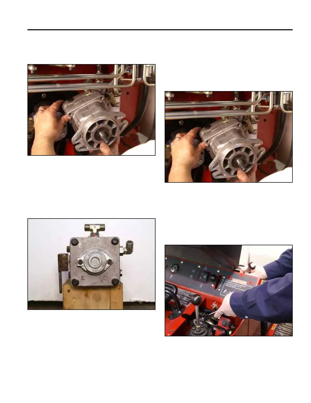
40. Remove the right hand hydrostatic pump from the
tower frame (Fig. 1368).
Fig 1368 PICT-4753
41. If replacing the pump, transfer all markings and
ttingstothenewpump(Fig.1369).
Note: DonotinstallthettingsmarkedDandE.
Fig 1369 PICT-4754a
42. If repairing/rebuilding the pump, refer to the Hydro-
Gear BDP-10A/16A/21L Hydrostatic Pumps Service
and Repair Manual (Toro Form No. 492-4789).
Right Hydrostatic Pump Installation
2. Using a 3/4” socket and wrench, install the top bolt
and nut. Tighten the lower bolt and nut securing the
right hand hydrostatic pump to the tower frame (Fig.
1371).
Fig 1371 PICT-8900
1. With the lower pump mounting bolt and nut loosely
installed in the tower frame, position the right hand
hydrostatic pump so the pump shaft is inserted
through the frame (Fig. 1370).
Fig 1370 PICT-4753