HYDRAULIC TESTING
9-1TX525 Service Manual Rev. 000
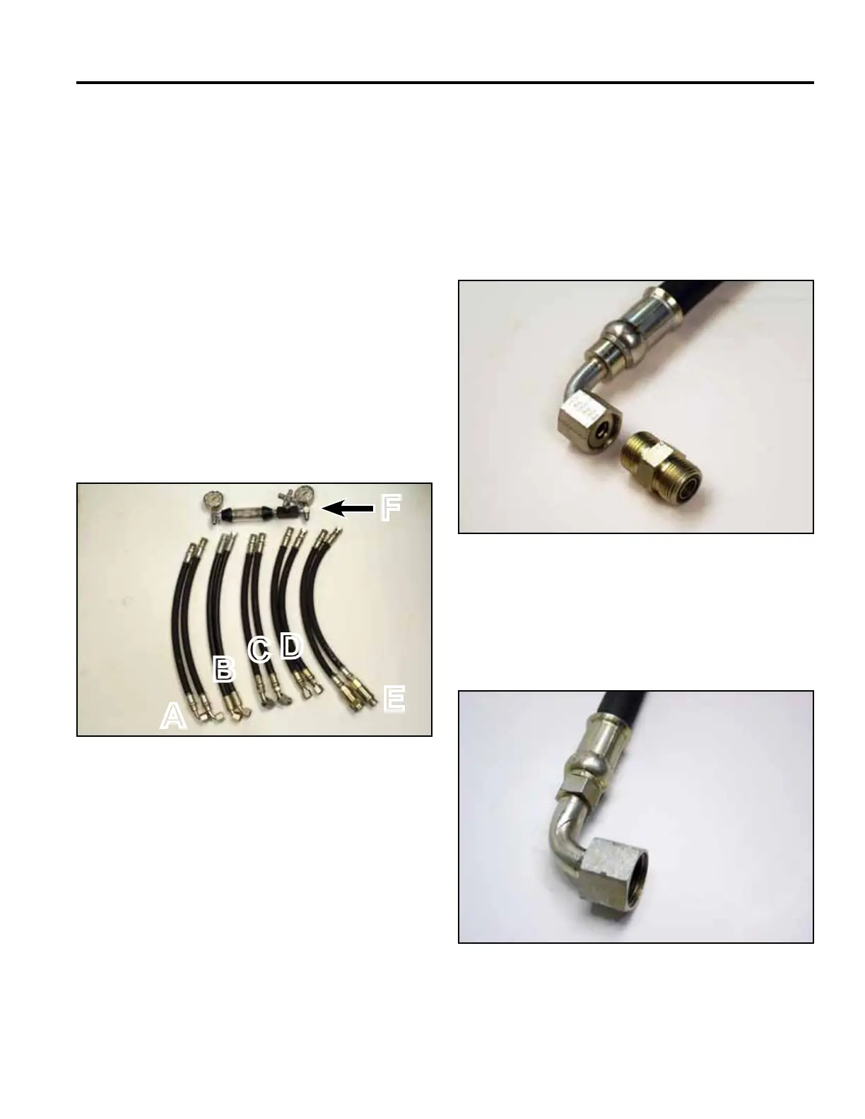
Fig 1837 PICT-4310a
The ve components listed A, B, C, D and E are the
primary testing locations for the TX models (Fig. 1837).
A. 2-Spool loader valve - C. LH Hydrostat
90º tting D. RH Hydrostat
B. 2-Spool loader valve - E. Flush face coupler
45º tting F. Flow meter
Due to the many types and manufacturers of test
equipment, the test hoses and ttings needed will vary.
Refer to the connection information at each hydraulic
test location.
Test hose specications must exceed maximum system
ow and pressure and must be compatible with the type
of uid in the hydraulic system.
TX525
Introduction
Flow Testing
Fig 1838 PICT-3521a
A. & B. 2-Spool Valve Hose Fitting and Coupler (Fig.
1838)
• Valve Hose Fitting - 13/16” - 16 ORFS 90º & 45º
• Valve Hose Fitting Coupler - 13/16” - 16 x 13/16”
ORFS
Note: ORFS = O-ring Face Seal
A
B
C
D
E
F
Fig 1839 DSC-0576a
C. LH Drive Hydrostat Pump
Pump Fitting – 1” - 14 ORFS – 90º Female (Fig. 1839)