HYDRAULIC SYSTEM
6-64 Rev. 000 TX525 Service Manual
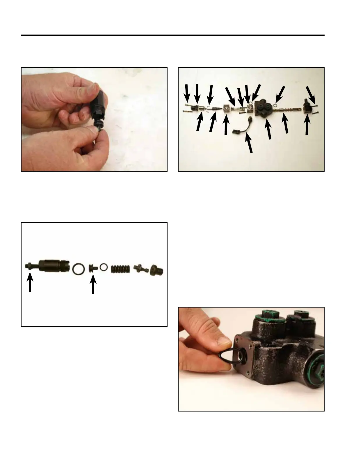
Relief Assembly
Spool Assembly
Auxiliary Valve Assembly
29. Remove the plunger from the relief (Fig. 1072).
Fig 1072 PICT-2706a
Fig 1074 PICT-2708a
1. Install the both spool o-rings into the valve body (Fig.
1075).
Fig 1075 PICT-2711
Fig 1073 PICT-2743a
A. Adjusting screw & nut E. Plunger O-ring
B. Body F. Spring
C. Body O-ring G. Relief plunger seat
D. Plunger H. Plunger body
A
B
C
D
E
F
G
H
A. Spring cap screws I. Switch block
B. Spring cap J. Spool O-ring
C. Detent collar K. Valve body
D. Detent balls L. Spool O-ring
E. Detent plunger M. Spool
F. Spring block N. Handle cap
G. Spring & retainers O. Handle cap screws
H. Switch block screws P. Detent switch
A
B
D
C
E
F
G H
I
J
K
L
M
N
O
P