HYDRAULIC SYSTEM
6-63TX525 Service Manual Rev. 000
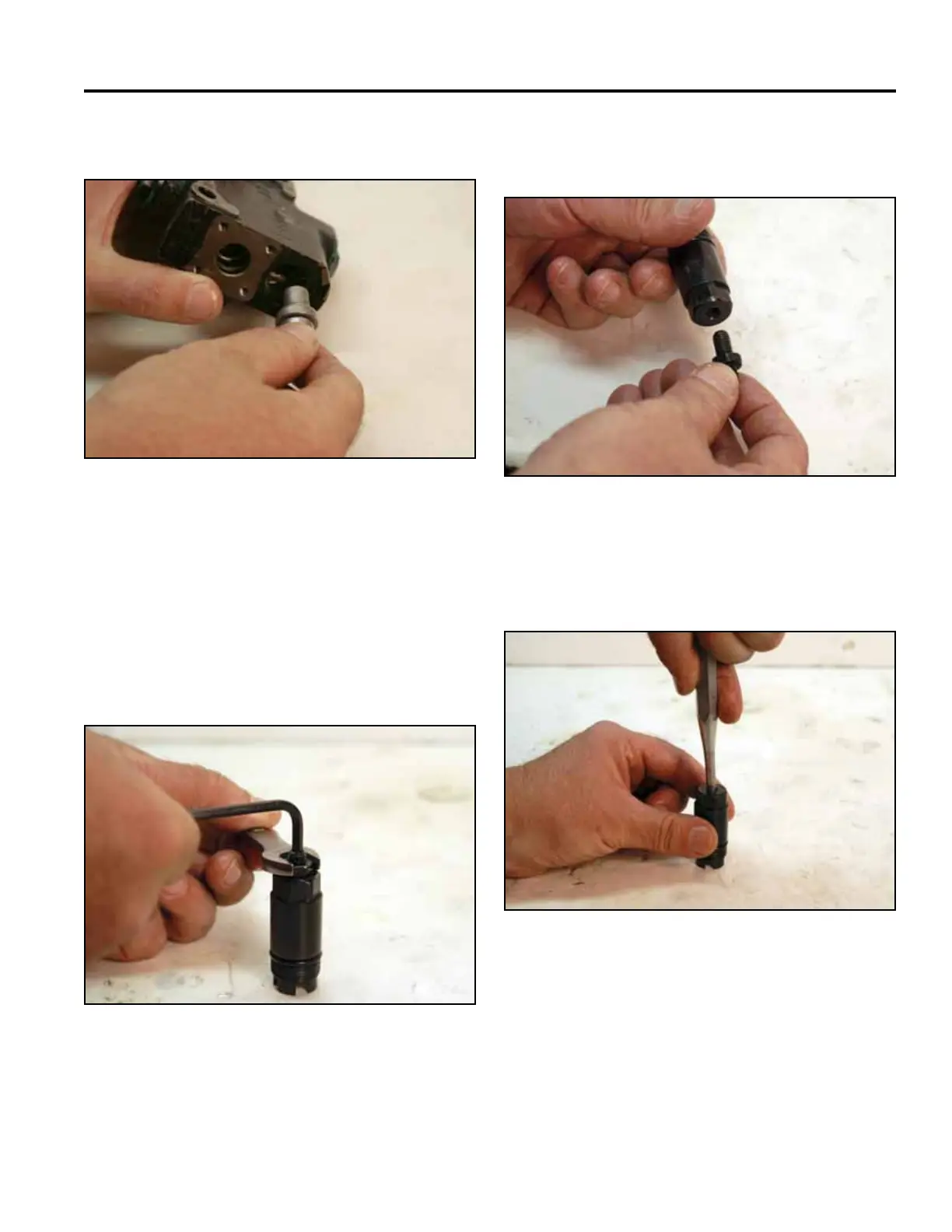
25. Remove the seat from the relief port (Fig. 1068). 27. Remove the adjusting screw from the relief barrel
(Fig. 1070).
Fig 1068 PICT-2702a
Fig 1070 PICT-2704a
28. Using a punch, push the plunger out of the relief
barrel (Fig. 1071).
26. Using a 4mm Allen wrench and a 13mm wrench,
loosen the adjusting screw from the relief (Fig.
1069).
Note: Changing the position of the adjusting screw
changes the relief pressure setting, which
must be checked after the auxiliary valve is
installed in the traction unit.
Fig 1071 PICT-2705a
Fig 1069 PICT-2703a