HYDRAULIC SYSTEM
6-62 Rev. 000 TX525 Service Manual
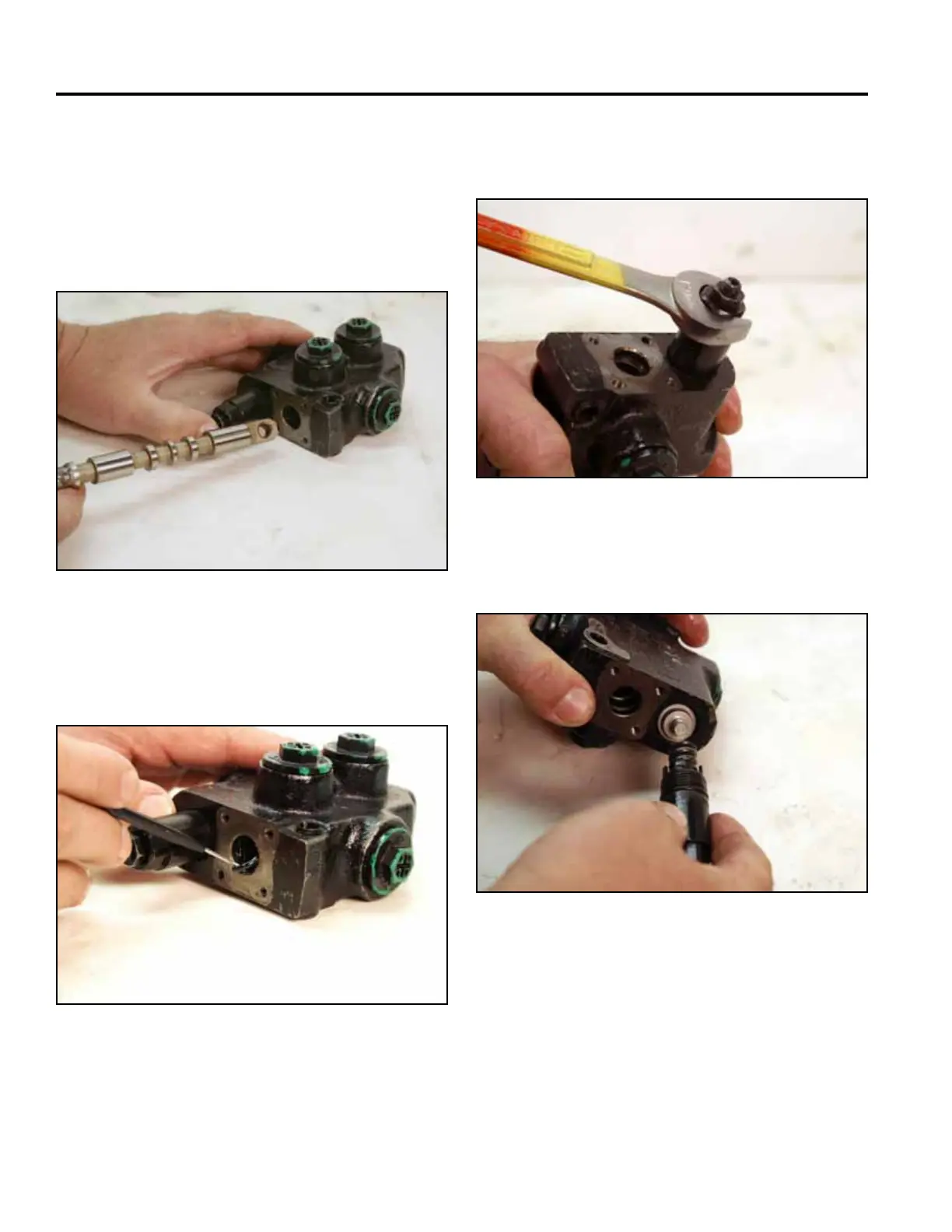
21. Remove the spool from the valve assembly (Fig.
1064).
Note: Inspect the spool and valve body bore. Re-
place the auxiliary valve assembly if damaged
or there are scratches deep enough to catch a
ngernail.
23. Using a 19mm wrench, continue loosening the relief
(Fig. 1066).
Fig 1064 PICT-2696a
Fig 1066 PICT-2699a
24. Remove the relief from the valve (Fig. 1067).
22. Remove both spool o-rings from the valve body (Fig.
1065).
Fig 1067 PICT-2700a
Fig 1065 PICT-2697