HYDRAULIC SYSTEM
6-61TX525 Service Manual Rev. 000
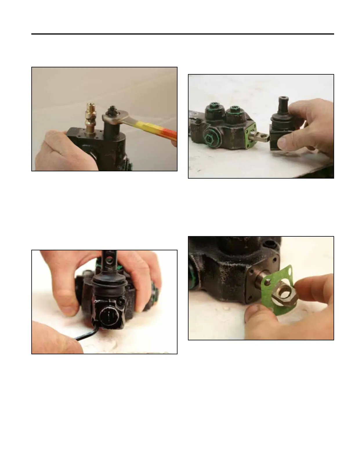
16. Using a 19mm wrench, loosen the relief (Fig. 1060). 19. Remove the operator lever block from the valve
assembly (Fig. 1062).
Fig 1060 PICT-2693a
Fig 1062 PICT-2741a
20. Remove the gasket from the valve assembly (Fig.
1063).
17. Remove the valve from the vise.
18. Using a 4mm Allen wrench, remove the 2 screws
retaining the operator lever spool cap from the valve
(Fig. 1061).
Fig 1063 PICT-2740
Fig 1061 PICT-2694