HYDRAULIC SYSTEM
6-60 Rev. 000 TX525 Service Manual
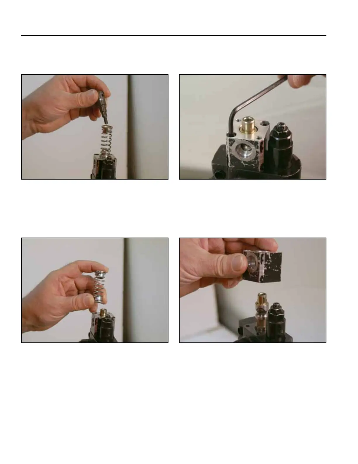
12. Remove the spring retainer from the valve assembly
(Fig. 1056).
14. Using a 4mm Allen wrench, remove 2 screws from
the switch block assembly (Fig. 1058).
Fig 1056 PICT-2688a
Fig 1058 PICT-2690a
15. Remove the switch block from the valve assembly
(Fig. 1059).
13. Remove the spring and retainers from the valve (Fig.
1057).
Fig 1059 PICT-2691a
Fig 1057 PICT-2689a