DRIVE SYSTEM
7-47TX525 Service Manual Rev. 000
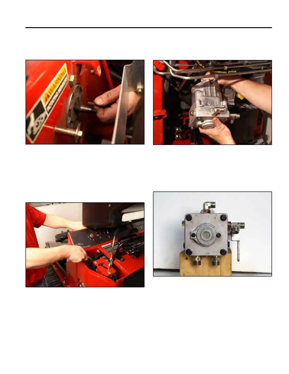
27. Remove the key from the hydrostatic pump shaft
keyway (Fig. 1439).
Fig 1439 PICT-4598
28. Using a 3/4” socket and wrench, remove the top bolt
and nut securing the left hand hydrostatic pump to
the tower frame. Loosen the lower nut and bolt (Fig.
1440).
Fig 1440 PICT-4619
29. Remove the left hand hydrostatic pump from the
tower frame (Fig. 1441).
31. If repairing/rebuilding the pump, refer to the Hydro-
Gear BDP-10A/16A/21L Hydrostatic Pumps Service
and Repair Manual (Toro Form No. 492-4789).
Fig 1441 PICT-4627
30. If replacing the pump, transfer all markings and
ttingstothenewpump(Fig.1442).
Fig 1442 PICT-4626a