HYDRAULIC SYSTEM
6-10 Rev. 000 TX525 Service Manual
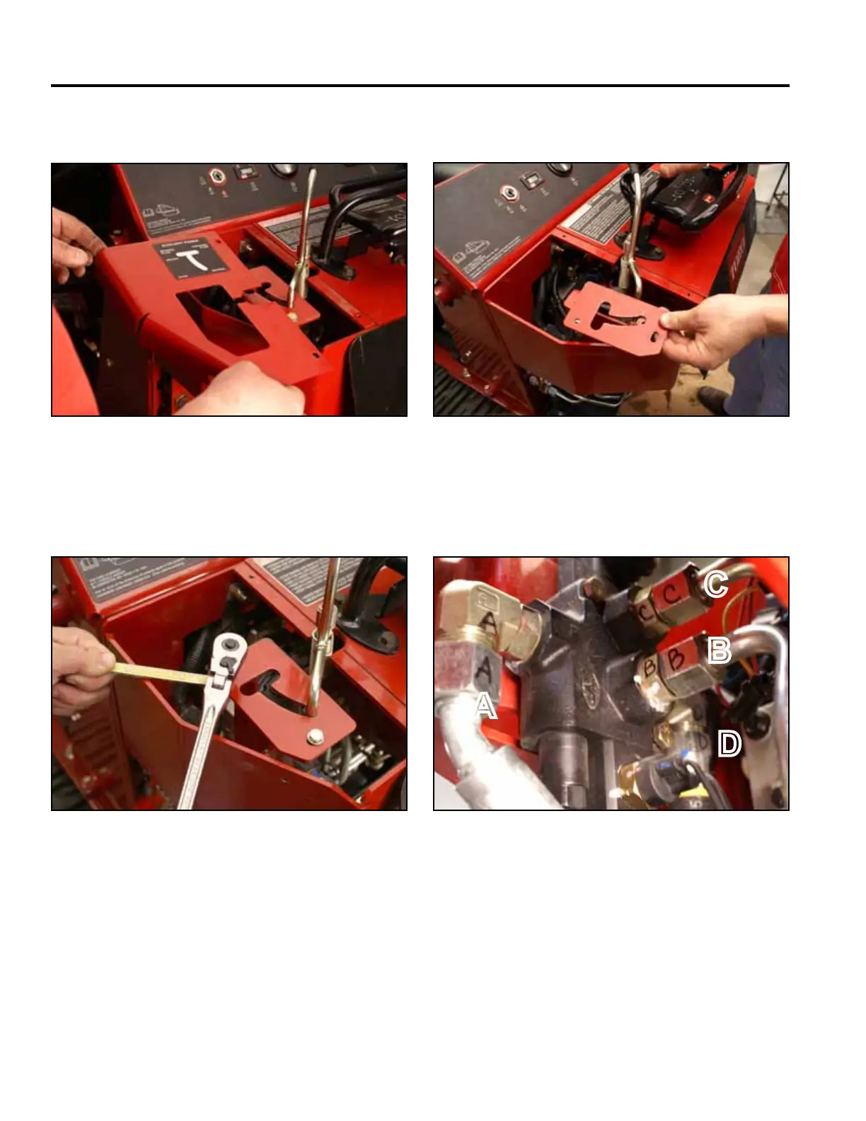
5. Remove the top left panel (Fig. 0865).
Fig 0865 PICT-4601
6. Using a 7/16” socket and wrench remove the 2 bolts,
washers and nuts from stop plate (Fig. 0866).
Fig 0866 PICT-4898a
7. Remove stop plate (Fig. 0867).
A. Inlet line from the tandem pump
B. Output line to the female coupler
C. Output line to the male coupler
D. Return oil to hydraulic oil cooler
Fig 0867 PICT-4899
8. Mark each auxiliary valve hydraulic line and tting
(Fig. 0868):
Fig 0868 PICT-4902
A
B
D
C