HYDRAULIC SYSTEM
6-24 Rev. 000 TX525 Service Manual
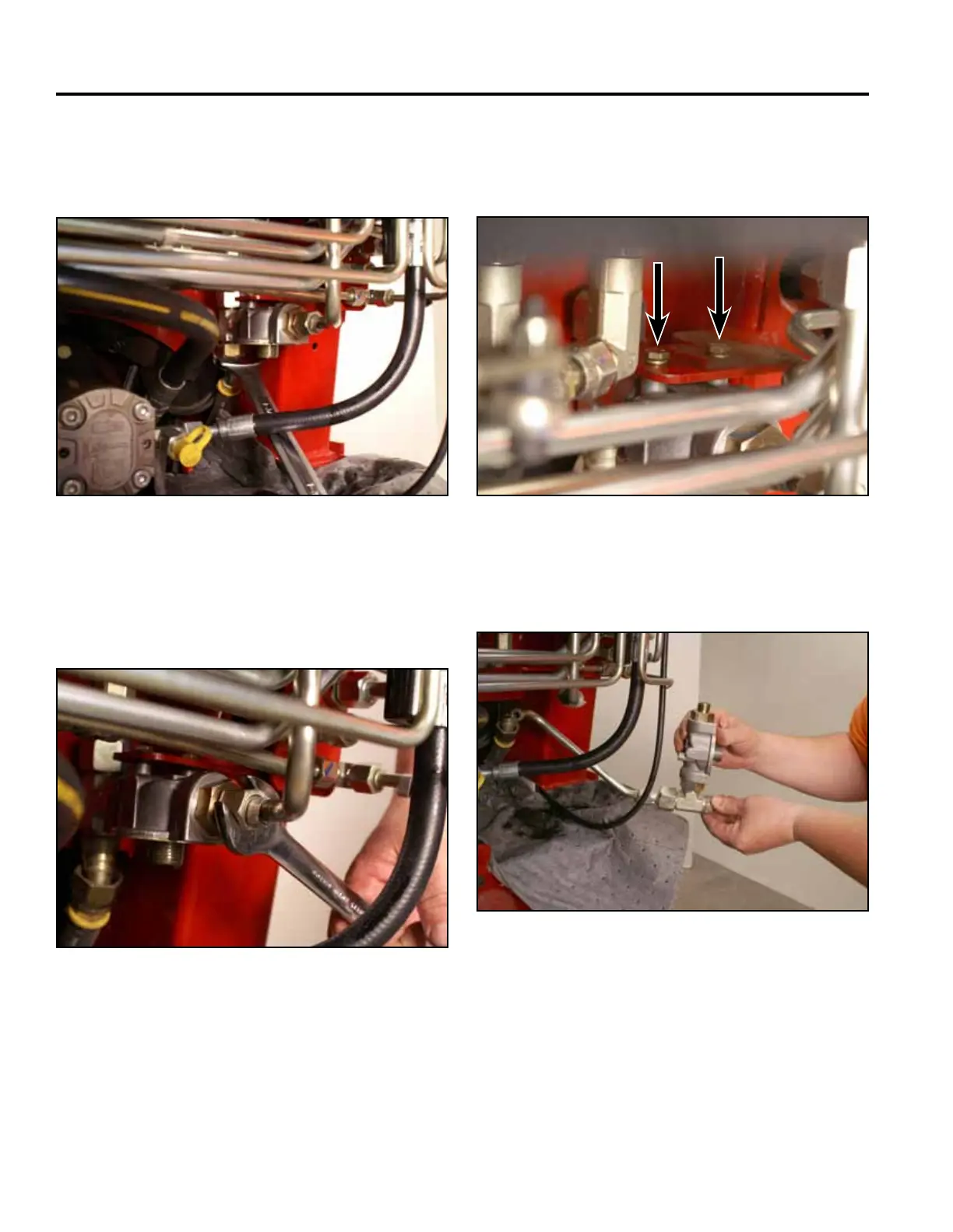
11. Using a 1-3/8” wrench, remove the hydraulic reser-
voir return line from the lter head T-tting (Fig.
0919).
13. Using a 1/2” wrench, remove the 2 bolts and wash-
ers securing the lter head to the mounting bracket
(Fig. 0921).
Fig 0919 PICT-4919
Fig 0921 PICT-4924a
14. Remove the lter head assembly (Fig. 0922).
12. Using a 15/16” wrench, remove the loader valve
hydraulic return line from the lter head tting (Fig.
0920).
Fig 0922 PICT-4926a
Fig 0920 PICT-4923