HYDRAULIC SYSTEM
6-91TX525 Service Manual Rev. 000
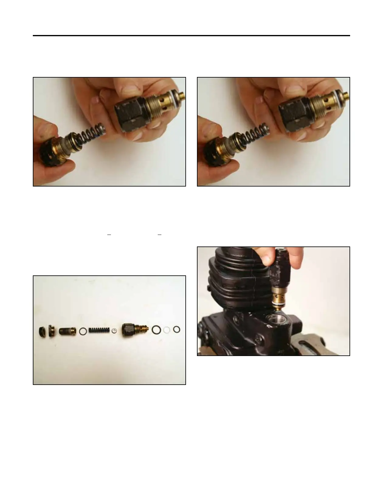
4. Disconnect the body of the main relief valve from the
main relief valve bonnet (Fig. 1179).
5. Connect the body of the main relief valve to the main
relief valve bonnet (Fig. 1181).
Fig 1179 PICT-2661a
Fig 1181 PICT-2661a
6. Using a 24mm wrench, install the main relief valve
into the valve assembly (Fig. 1182).
The relief valve is used to adjust to the specied
system pressure (2400 + 50 psi or 165.47 + 3.45
bar) by increasing or decreasing the load on the
spring against the disc. Loosen the lock nut; turn
screw inward to increase the pressure or outward to
decrease the pressure (Fig. 1180).
Fig 1182 PICT-2657a
Fig 1180 PICT-2659a
A. Bonnet F. Spring spacer
B. Set screw lock nut G. Body
C. Set screw H. Body o-ring
D. Set screw o-ring I. Back up o-ring
E. Spring J. O-ring
A
B
C
D
E
F
G
H J
I