HYDRAULIC SYSTEM
6-104 Rev. 000 TX525 Service Manual
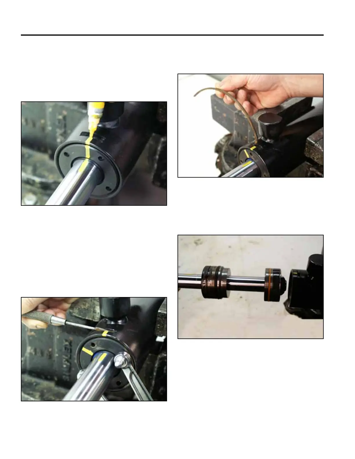
Note: If excessive wear due to side-loads or binding
is a possibility, mark or note the piston and
head relationship to the rod and tube. This
condition will usually show up as a highly
polished surface on the piston and head 90°
to the pin rotation axis (Fig. 1226).
6. Continue to rotate the head counter-clockwise until
the retaining ring is completely removed (Fig. 1228).
Fig 1226 PICT-2953
Fig 1228 PICT-2957
7. Pull out on the rod to remove the piston and head
assembly from the barrel (Fig. 1229).
5. Using a spanner wrench installed in the holes pro-
vided, rotate the head clockwise until the beveled
edge of the retaining ring appears in the milled
opening of the tube. Insert a at blade screwdriver
between the beveled edge of the retaining ring and
the cylinder barrel to start the retaining ring through
the opening (Fig. 1227).
Fig 1229 PICT-2958a
Fig 1227 PICT-2956