DRIVE SYSTEM
7-14 Rev. 000 TX525 Service Manual
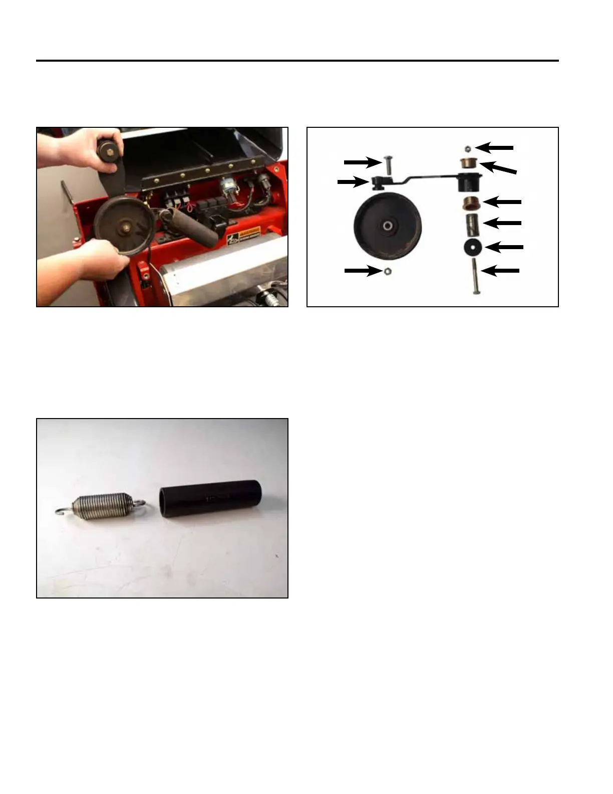
11. Remove the idler arm assembly from the unit (Fig.
1310).
13. Inspecttheidlerpulleybearingandthetwoange
bushings. Replace if worn or damaged (Fig. 1312).
Fig 1310 PICT-5371 Fig 1312 CLR DSC-3321
A. Carriage bolt F. Flange bushings (2)
B. Idler arm assembly G. Mounting spacer
C. Pulley H. Washer
D. Nut I. Bolt
E. Nut
12. Remove the spring and rubber spring retainer from
the idler assembly and slide the rubber spring
retainer off the spring (Fig. 1311).
Fig 1311 PICT-5374a
DSC-3321 (found in the TX420/425
manual – “Drive” section, pg 8-55)
A
E
F
F
G
H
I
D
B
C