DRIVE SYSTEM
7-96 Rev. 000 TX525 Service Manual
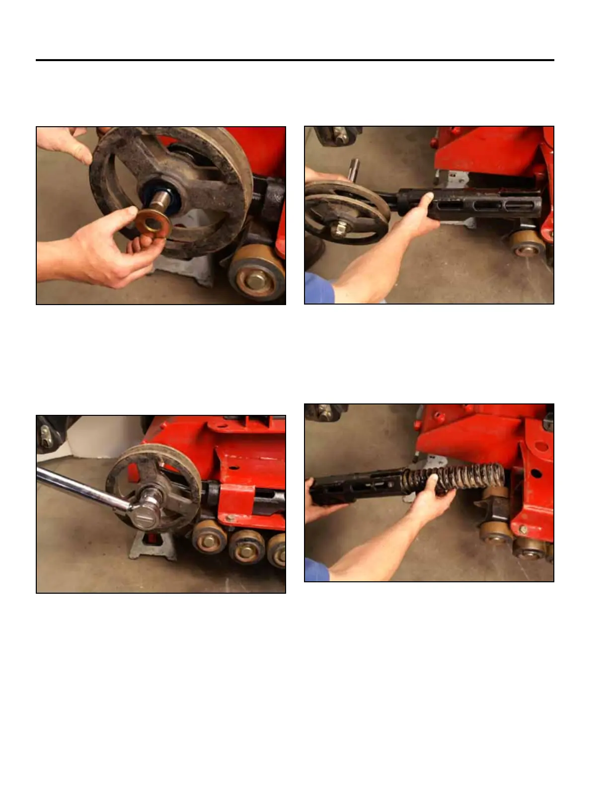
10. Place a washer into the greased wheel bore (Fig.
1618).
12. Slide the tensioner arm assembly out of the main-
frame (Fig. 1620).
Fig 1618 PICT-4581
Fig 1620 PICT-4584
13. Slide the tensioner spring into the tensioner arm
(Fig. 1621).
11. Using a 1-1/2” socket, install a nut securing the ten-
sioner wheel to the tensioner arm shaft. Torque the
nut to 300 ft-lbs. (407 Nm) (Fig. 1619).
Fig 1621 PICT-4585
Fig 1619 PICT-4583