DRIVE SYSTEM
7-98 Rev. 000 TX525 Service Manual
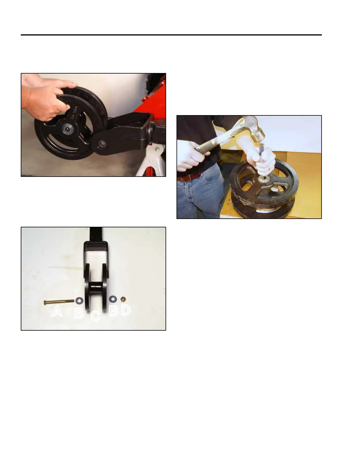
5. Remove the tensioner wheel from the tensioner arm
(Fig. 1625).
Fig 1625 PICT-5348
Tensioner Wheel Assembly (Fig. 1626):
Fig 1626 PICT-5354a
6. Support the tensioner wheel so there is a space
under it for bearing removal. Using a hammer, drive
the upper bearing down to create a gap between
spacer and bearing, then use a drift punch to ham-
mer the lower bearing out. The spacer will fall out
when the bearing is removed. Turn the tensioner
wheel over and drive out the other bearing. Inspect
the tensioner wheel housing and spacer (Fig. 1627).
Fig 1627 CLR DSC-0808
A. Bolt C. Tensioner wheel
B. Washer (2) D. Nut
A
C
B
B
D