BRAKES
8-49TX525 Service Manual Rev. 000
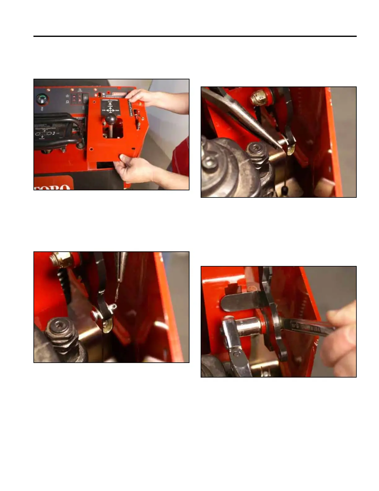
4. Remove the right panel from the control panel
assembly (Fig. 1816).
6. Support the brake handle and remove the clevis pin
that retains the brake cable to the brake handle (Fig.
1818).
Fig 1816 PICT-4343a
Fig 1818 PICT-4425
7. Using a 9/16” socket and wrench, remove the nut
from the shoulder bolt securing the brake handle to
the control panel bracket (Fig. 1819).
5. Remove the cotter pin from the clevis pin attaching
the brake cable to the brake handle (Fig. 1817).
Fig 1819 PICT-4426a
Fig 1817 PICT-4424