Pin Function
1STARTIN
2ABORTIN
3BCD1IN
4BCD3IN
5BCD5IN
6BCD7IN
7 PASS1+
8FAIL1+
9 READY+
10 EOC+
11 ALARM+
12 NOT USED
13 NOT USED
14 ENTSTIN (START ENABLE)
15 BCD0IN
16 BCD2IN
17 BCD4IN
18 BCD6IN
19 INRTN
20 PASS1-
21 FAIL1-
22 READY-
23 EOC-
24 ALARM-
25 NOT USED
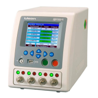
Pin 1
Pin 25
Operation of the standard I/O is as
follows:
The inputs are opto-isolators requiring
24VDC power with respect to pin 19
(INRTN). The outputs are dry contact
relays. If desired, it is possible to
supply 24VDC to the (-) side of each of
the outputs, and then when the output
is asserted, there would be a 24VDC
signal present on the (+) side.