8-40 Phaser 7750 Printer Service Manual
Electrical Chassis (Card Cage) Assembly
Note
Before removing the electrical chassis assembly, it is recommended you
store the Engine NVRAM data to the hard drive. See "Store Engine
NVRAM" on page 6-21.
1. Remove the right cover, see page 8-4.
2. Remove the top cover, see page 8-5.
3. Remove the rear cover, see page 8-6.
4. Remove all 3 shields on the rear of the printer.
5. Remove the image processor board, see page 8-38.
6. Disconnect the 9 wiring harnesses along the edges of the engine controller board.
7 of these harnesses are in front of the controller board. The other 2 are on the left
side.
7. Two of the engine control connectors have connector locks. There is 1 harness
clip to release.
8. Undo the harness retainer. Disconnect the wiring harness to the relay board
connector P300 and the front panel cable to P564.
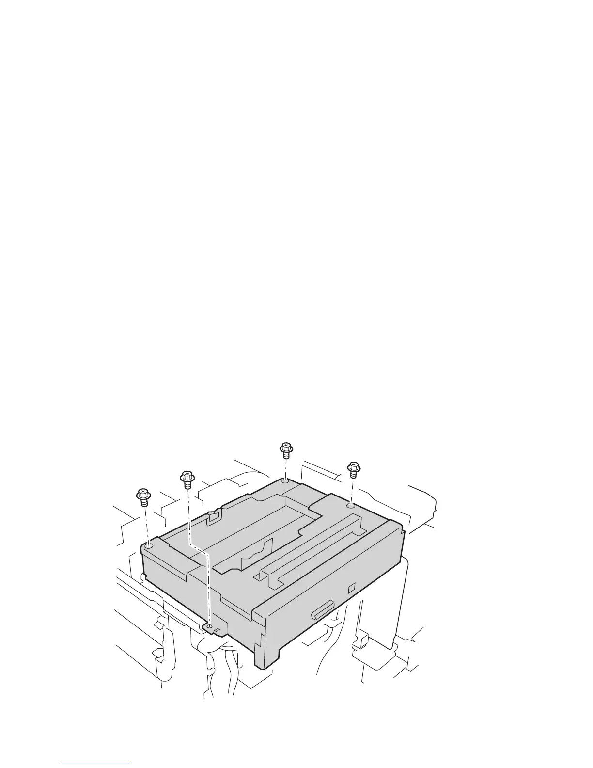
9. Remove the 2 mounting screws towards the rear of the printer, but only loosen the
two mounting screws towards the printer front.
Note
The 2 screws toward the printer front serve as a guide for reinstallation.
7750-027
 Loading...


