February, 2008
6-35
WorkCentre 5225, 5230
IIT NVM List
General Procedures
Launch Version
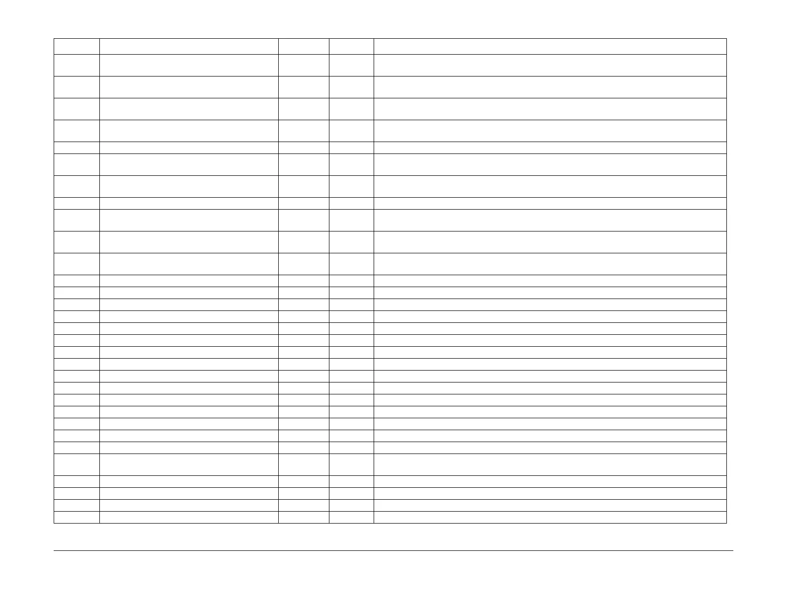
715-110 CVT FS Offset Side1 120 0~240 Fast Scan Direction Regi Correction Value (2dot/increment) in CVT. Factory Settings. When the
power is turned on, the value changes to that of DADF NVM (711-272).
715-111 CVT FS Offset Side2 120 0~240 Fast Scan Direction Regi Correction Value (2dot/increment) in CVT. Factory Settings. When the
power is turned on, the value changes to that of DADF NVM (711-274).
715-112 CVT FS Offset Side3 120 0~240 Fast Scan Direction Regi Correction Value (2dot/increment) in CVT. Factory Settings. When the
power is turned on, the value changes to that of DADF NVM (711-274).
715-113 CVT FS Offset Side4 120 0~240 Fast Scan Direction Regi Correction Value (2dot/increment) in CVT. Factory Settings. When the
power is turned on, the value changes to that of DADF NVM (711-274).
715-201 ACS Detection Level Extension 0 0~1 0: Normal, 1: Extends levels to be detected
715-241 Black Line Correction Level Value (for Color) 8 0~15 Black Line Correction Strength Level Setting when reading Color, the larger the value, the stronger
the correction strength (“0” means no correction).
715-242 Black Line Correction Level Value (for BW) 9 0~15 Black Line Correction Strength Level Setting when reading BW, the larger the value, the stronger
the correction strength (“0” means correction reset).
715-243 DCIC TEST MODE 0 0~7 Test Mode Setting for Designing Black Line Correction Parameter, “0” means normal operation.
715-244 BWC Table 0 0~7 B/W correction table for registration by customers. (BWC) B/W correction is not performed by set-
ting “0.”
715-245 Sampling timing optimization 0 0~1 Optimizes the timing of image sampling. The optimization starts only when 1 is written. *When val-
ues other than 1 are entered, the values are invalid.
715-246 Threshold level of tuning 4 1~7 Threshold value for density difference that is used when calculating the optimal timing of image
sampling. Can be changed between 1 and 7.
715-280 HOSEI_SCAN 3 0~6 Correction coefficient number. *The value adjusted at shipment is applied.
715-281 HOSEI_SCAN 3 0~6 Correction coefficient number. *The value adjusted at shipment is applied.
715-282 CCD Calib Y Scan Red 0 0~1023 CCD Calibration. Red at the time of scanning Y patch (reflectance LSB). *Recorded at shipment.
715-283 CCD Calib Y Scan Green 0 0~1023 CCD Calibration. Green at the time of scanning Y patch (reflectance LSB). *Recorded at shipment.
715-284 CCD Calib Y Scan Blue 0 0~1023 CCD Calibration. Blue at the time of scanning Y patch (reflectance LSB). *Recorded at shipment.
715-285 CCD Calib M Scan Red 0 0~1023 CCD Calibration. Red at the time of scanning M patch (reflectance LSB). *Recorded at shipment.
715-286 CCD Calib M Scan Green 0 0~1023 CCD Calibration. Green at the time of scanning M patch (reflectance LSB). *Recorded at shipment.
715-287 CCD Calib M Scan Blue 0 0~1023 CCD Calibration. Blue at the time of scanning M patch (reflectance LSB). *Recorded at shipment.
715-288 CCD Calib C Scan Red 0 0~1023 CCD Calibration. Red at the time of scanning C patch (reflectance LSB). *Recorded at shipment.
715-289 CCD Calib C Scan Green 0 0~1023 CCD Calibration. Green at the time of scanning C patch (reflectance LSB). *Recorded at shipment.
715-290 CCD Calib C Scan Blue 0 0~1023 CCD Calibration. Blue at the time of scanning C patch (reflectance LSB). *Recorded at shipment.
715-291 CCD Calib PK Scan Red 0 0~1023 CCD Calibration. Red at the time of scanning PK patch (reflectance LSB). *Recorded at shipment.
715-292 CCD Calib PK Scan Green 0 0~1023 CCD Calibration. Green at the time of scanning PK patch (reflectance LSB). *Recorded at shipment.
715-293 CCD Calib PK Scan Blue 0 0~1023 CCD Calibration. Blue at the time of scanning PK patch (reflectance LSB). *Recorded at shipment.
715-302 A4S/8.5in Detection 2 3 0~6 0: 210mm, 1: 211mm, 2: 212mm, 3: 213mm, 4: 214mm, 5: 215mm, 6: 216mm
715-303 B5/8x10 Detection 0 0~3 0: Table default 1: B5LEF or ExecutiveLEF 2: 8x10LEF/8x10.5LEF 3: This value is for design test.
Performance is not guaranteed.
715-305 8.5x13/8.5x14 Detection 0 0~3 0: Table default. 1: This value is for design test. Performance is not guaranteed. 2: 13inch 3: 14inch
715-306 Original Detection Table for Special Paper 0 0~2 0: Do not use Special Table 1: APS OFF, A4; APS ON, A3 2: APS OFF, Letter; APS ON, 17inch
715-307 Original Size Detection Table Switch 2 1~5 1: Inch13-2 2: mm-2 3: mm 4: Inch13-1 5: Inch14
715-308 5.5x8.5/Postcard Detection 0 0~2 0: Table default 1: A5SEF or 5.5x8.5SEF 2: PostCardLEF
Table 2 IISS
Chain-Link Content Default Range Meaning

 Loading...
