5-25
VALVES AND VALVE SPRINGS
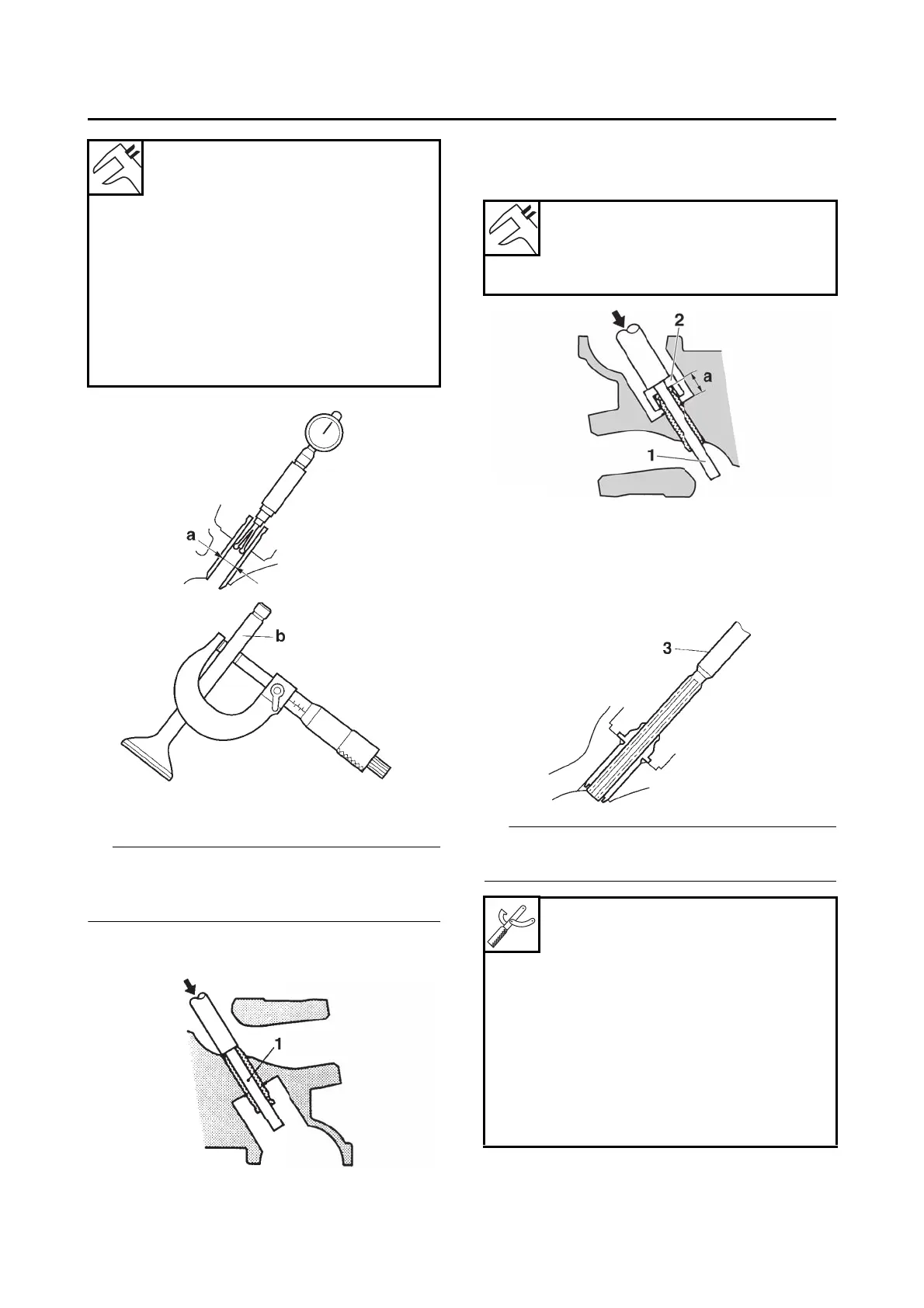
2. Replace:
• Valve guide
To ease valve guide removal and installation,
and to maintain the correct fit, heat the cylinder
head to 100 C (212 F) in an oven.
a. Remove the valve guide with the valve
guide remover “1”.
b. Install the new valve guide with the valve
guide installer “2” and valve guide remover
“1”.
c. After installing the valve guide, bore the
valve guide with the valve guide reamer “3”
to obtain the proper valve-stem-to-valve-
guide clearance.
After replacing the valve guide, reface the valve
seat.
Valve-stem-to-valve-guide clear-
ance (intake)
0.010–0.037 mm (0.0004–0.0015
in)
Limit
0.080 mm (0.0032 in)
Valve-stem-to-valve-guide clear-
ance (exhaust)
0.025–0.052 mm (0.0010–0.0020
in)
Limit
0.100 mm (0.0039 in)
Valve guide position (intake)
12.2–12.6 mm (0.48–0.50 in)
Valve guide position (exhaust)
12.2–12.6 mm (0.48–0.50 in)
a. Valve guide position
Valve guide remover (ø4)
90890-04111
Valve guide remover (4.0 mm)
YM-04111
Valve guide installer (ø4)
90890-04112
Valve guide installer (4.0 mm)
YM-04112
Valve guide reamer (ø4)
90890-04113
Valve guide reamer (4.0 mm)
YM-04113
 Loading...