9-145
P0657
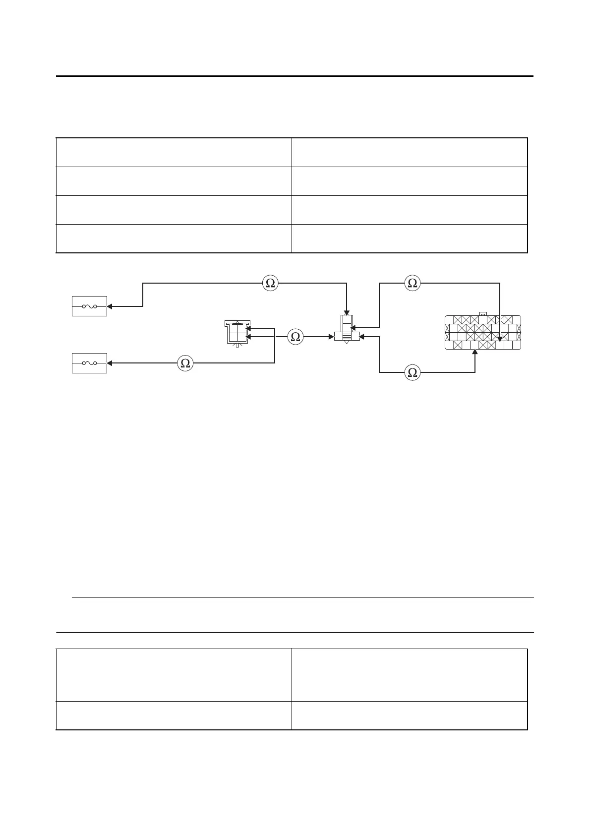
3. Wire harness continuity.
• Disconnect the fuel injection system fuse, fuel injection system relay coupler, ignition fuse, handle-
bar switch coupler (right) and ECU coupler.
• Open circuit check
• Short circuit check
Disconnect the ECU related connectors before checking.
Refer to “PARTS CONNECTED TO THE ECU” on page 9-3.
Ground short circuit check “A”
Between fuel injection system fuse holder “1”
and fuel injection system relay coupler “2”
red–red
Between ignition fuse holder “3” and handlebar
switch coupler (right) “4”
red/white–red/white
Between handlebar switch coupler (right) “4”
and fuel injection system relay coupler “2”
red/black–red/black
Between fuel injection system relay coupler “2”
and ECU coupler “5”
red/blue–red/blue
blue/yellow–blue/yellow
Is resistance 0 ?
YES
Go to “Short circuit check”.
NO
a. Replace the wire harness.
b. Start the engine and let it idle for approximately 5 seconds.
c. Check the condition of the DTC using the malfunction mode of the YDT.
Is it in the “Recovered” condition?
YES
Go to step 7, and complete the service.
NO
Go to “Short circuit check”.
Between fuel injection system relay coupler “2”
and ground
red–ground
red/blue–ground
blue/yellow–ground
red/black–ground
Between handlebar switch coupler (right) “4”
and ground
red/white–ground
red/black–ground
O
B/GY/R
B
R/BG/B
Y/W
B
Y/RR/L
BB
R/LL/Y
Y/W
R
R
R/L
R/B
L/Y
Br/Y R/W
Br/W
R/B
1
3
4
25
 Loading...