Step Display/Result
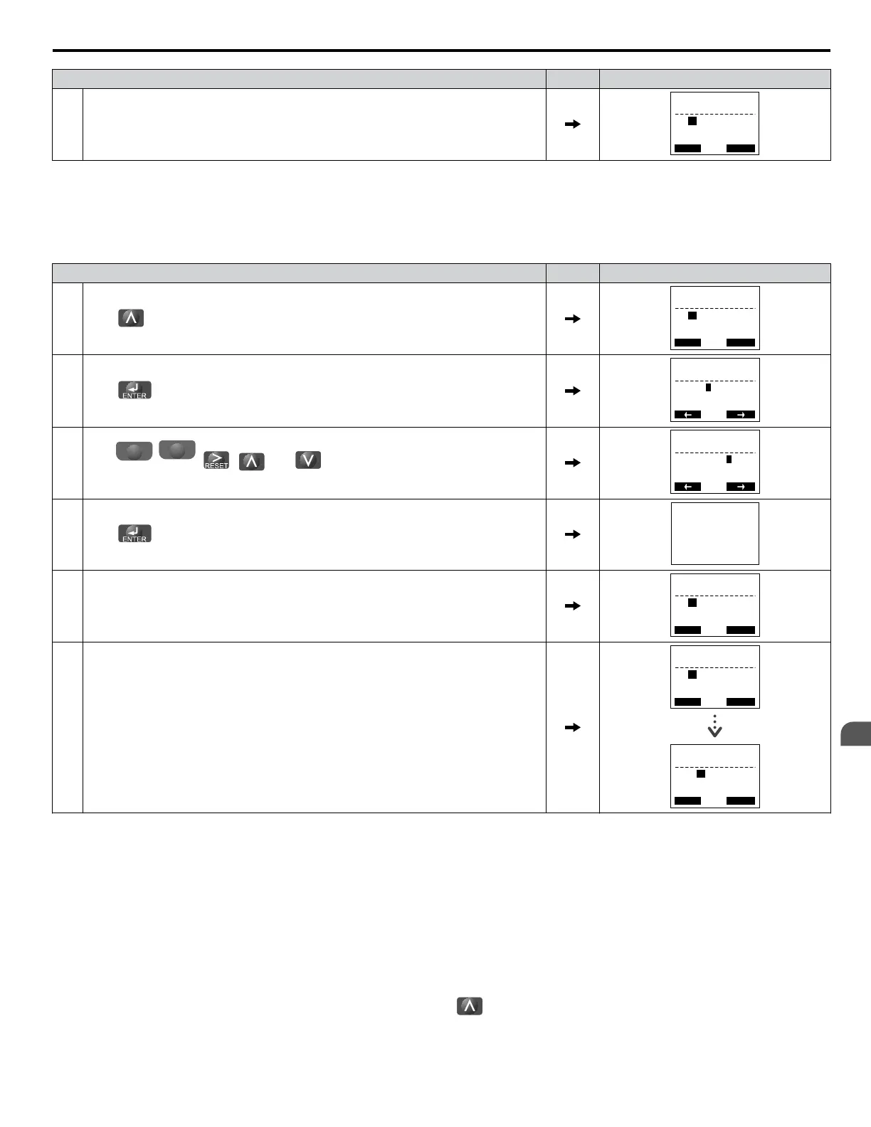
6. The display automatically returns to the display shown in Step 3.
- A.TUNE -
T1-01= 0 *0*
Standard Tuning
PRG
Tuning Mode Sel
Rdy
ESC FWD DATA
<1>
T1-00 will appear on the display when one of the multi-function inputs has been set to switch between motor 1 and motor 2 (H1-oo = 16).
n
Enter Data from the Motor Nameplate
After selecting the type of Auto-Tuning, enter the data required from the motor nameplate.
Note: These instructions continue from Step 6 in “Selecting the Type of Auto-Tuning”.
Step Display/Result
1.
Press to access the motor output power parameter T1-02.
- A.TUNE -
T1-02= 0.75kW
(0 00 ~ 650 00)
PRG
Mtr Rated Power
Rdy
ESC FWD DATA
“0.75kW”
2.
Press
to view the default setting.
- A.TUNE -
T1-02= 000.75kW
(0 00 ~ 650 00)
PRG
Mtr Rated Power
Rdy
FWD
“0.75kW”
3.
Press
F1
left
,
F2
right
,
, , and to enter the motor power nameplate data in
kW.
- A.TUNE -
T1-02= 000.40kW
(0 00 ~ 650 00)
PRG
Mtr Rated Power
Rdy
FWD
“0.75kW”
4.
Press
to save the setting.
Entry Accepted
5. The display automatically returns to the display in Step 1.
- A.TUNE -
T1-02= 0.40kW
(0 00 ~ 650 00)
PRG
Mtr Rated Power
Rdy
ESC FWD DATA
“0.75kW”
6.
Repeat Steps 1 through 5 to set the following parameters:
• T1-03, Motor Rated Voltage
• T1-04, Motor Rated Current
• T1-05, Motor Base Frequency
• T1-06, Number of Motor Poles
• T1-07, Motor Base Frequency
• T1-09, Motor No-Load Current (Stationary Auto-Tuning 1 or 2 only)
• T1-10, Motor Rated Slip (Stationary Auto-Tuning 2 only)
- A.TUNE -
T1-
10
= X.XX Hz
(0 00 ~ 20.00)
PRG
Mtr Rated Slip
ESC FWD DATA
“X XX Hz”
- A.TUNE -
T1-03= 200 0VAC
(0 0 ~ 255.0)
PRG
Rated Voltage
ESC FWD DATA
“200.0VAC”
Note: 1. For details on each setting, Refer to Parameter Settings during Induction Motor Auto-Tuning: T1 on page 106.
2. To execute Stationary Auto-Tuning for line-to-line resistance only, set parameters T1-02 and T1-04.
n
Starting Auto-Tuning
WARNING! Sudden Movement Hazard. The drive and motor may start unexpectedly during Auto-Tuning, which could result in death or
serious injury. Ensure the area surrounding the drive motor and load are clear before proceeding with Auto-Tuning.
WARNING! Electrical Shock Hazard. High voltage will be supplied to the motor when Stationary Auto-Tuning is performed even with the
motor stopped, which could result in death or serious injury. Do not touch the motor until Auto-Tuning has been completed.
NOTICE: Rotational
Auto-Tuning will not function properly if a holding brake is engaged on the load. Failure to comply could result in improper
operation of the drive. Ensure the motor can freely spin before beginning Auto-Tuning.
Enter the required information from the motor nameplate. Press
to proceed to the Auto-Tuning start display.
Note: These instructions continue from Step 6 in “Enter Data from the Motor Nameplate”.
4.7 Auto-Tuning
YASKAWA ELECTRIC SIEP C710616 31B YASKAWA AC Drive – A1000 Technical Manual
105
4
Start-Up Programming
& Operation

 Loading...


