u
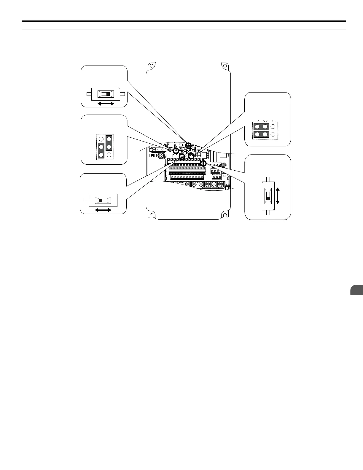
Switches and Jumpers on the Terminal Board
The terminal board is equipped with several switches used to adapt the drive I/Os to the external control signals. Figure
3.20 shows the location of these switches. Refer to Control I/O Connections on page 68 for setting instructions.
V I
DIP Switch S1
Terminal A2 Signal
Selection
PTC
AI
DIP Switch S4
Terminal A3 Analog/
PTC Input Sel.
Jumper S5
Terminal AM/FM Signal
Selection
Jumper S3
Terminal H1/H2
Sink/Source Sel.
D P Switch S2
RS-422/485 Termination
Resistor
Off On
V
AM
FM
I
Figure 3.20 Locations of Jumpers and Switches on the Terminal Board
3.9 Control Circuit Wiring
YASKAWA ELECTRIC SIEP C710616 31B YASKAWA AC Drive – A1000 Technical Manual
67
3
Electrical Installation

 Loading...


