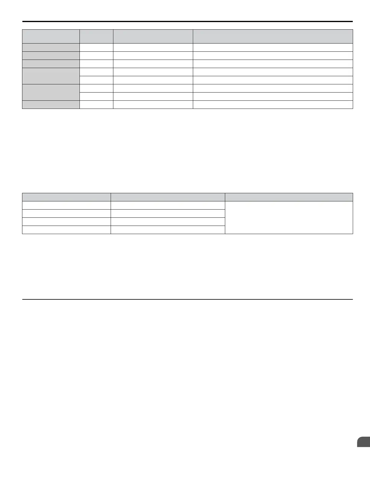
Wire Gauge
mm
2
(AWG)
Terminal
Screws
Crimp Terminal
Model Numbers
Tightening Torque
N m (lb to in.)
50/60 (1/ 1/0) M12 R60-12 32.0 to 40.0 (284.0 to 354.0)
80 (2/0) M12 R80-12 32.0 to 40.0 (284.0 to 354.0)
100 (4/0) M12 R100-12 32.0 to 40.0 (284.0 to 354.0)
150 (250/300MCM)
M10 150-10 18.0 to 23.0 (159.0 to 204.0)
M12 150-12 32.0 to 40.0 (284.0 to 354.0)
200 (400MCM)
M10 200-10 18.0 to 23.0 (159.0 to 204.0)
M12 R200-12 32.0 to 40.0 (284.0 to 354.0)
325 (600/650MCM) M12 325-12 32.0 to 40.0 (284.0 to 354.0)
<1>
Use the specified crimp terminals (Model 14-NK4) when using CIMR-Ao5A0011, with 6 AWG (14 mm
2
).
Note: Use crimp insulated terminals or insulated shrink tubing for wiring connections. Wires should have a continuous maximum allowable
temperature of 75 °C 600 Vac UL-approved vinyl-sheathed insulation.
Input Fuse Installation
Always install fuses at the drive input side. Refer to Installing Input Fuses on page 369 for selecting fuses.
n
Low Voltage Wiring for Control Circuit Terminals
Wire low voltage wires with NEC Class 1 circuit conductors. Refer to national, state, or local codes for wiring. Use a class 2
(UL regulations) power supply for the control circuit terminal when not using the internal control power supply of the drive.
Table D.2 Control Circuit Terminal Power Supply
Input / Output Terminal Signal Power Supply Specifications
Multi-function digital inputs S1, S2, S3, S4, S5, S6, S7, S8, SC
Use the internal control power supply of the drive or an
external class 2 power supply.
Multi-function analog inputs A1, A2, A3, AC
Pulse train input RP, AC
Pulse train output MP, AC
n
Drive Short Circuit Rating
This drive has undergone the UL short circuit test, which certifies that during a short circuit in the power supply, the current
flow will not rise above 100,000 amps at 600 V for 600 V class drives.
• The circuit breaker protection and fuse ratings shall be equal to or greater than the short-circuit tolerance of the power supply
being used.
• Suitable for use on a circuit capable of delivering not more than 100,000 RMS symmetrical amperes for 600 V in 600 V
class drives motor overload protection.
u
Drive Motor Overload Protection
Set parameter E2-01 (motor rated current) to the appropriate value to enable motor overload protection. The internal motor
overload protection is UL listed and in accordance with the NEC and CEC.
n
E2-01: Motor Rated Current
Setting Range: Model-dependent
Default Setting: Model-dependent
Parameter E2-01 protects the motor when parameter L1-01 is not set to 0. The default for L1-01 is 1, which enables protection
for standard induction motors.
If Auto-Tuning has been performed successfully, the motor data entered to T1-04 is automatically written to parameter E2-01.
If Auto-Tuning has not been performed, manually enter the correct motor rated current to parameter E2-01.
n
L1-01: Motor Overload Protection Selection
The drive has an electronic overload protection function (oL1) based on time, output current, and output frequency that protects
the motor from overheating. The electronic thermal overload function is UL-recognized, so it does not require an external
thermal relay for single motor operation.
This parameter selects the motor overload curve used according to the type of motor applied.
D.2 UL Standards
YASKAWA ELECTRIC SIEP C710616 31B YASKAWA AC Drive – A1000 Technical Manual
499
D
Standards Compliance

 Loading...


