u
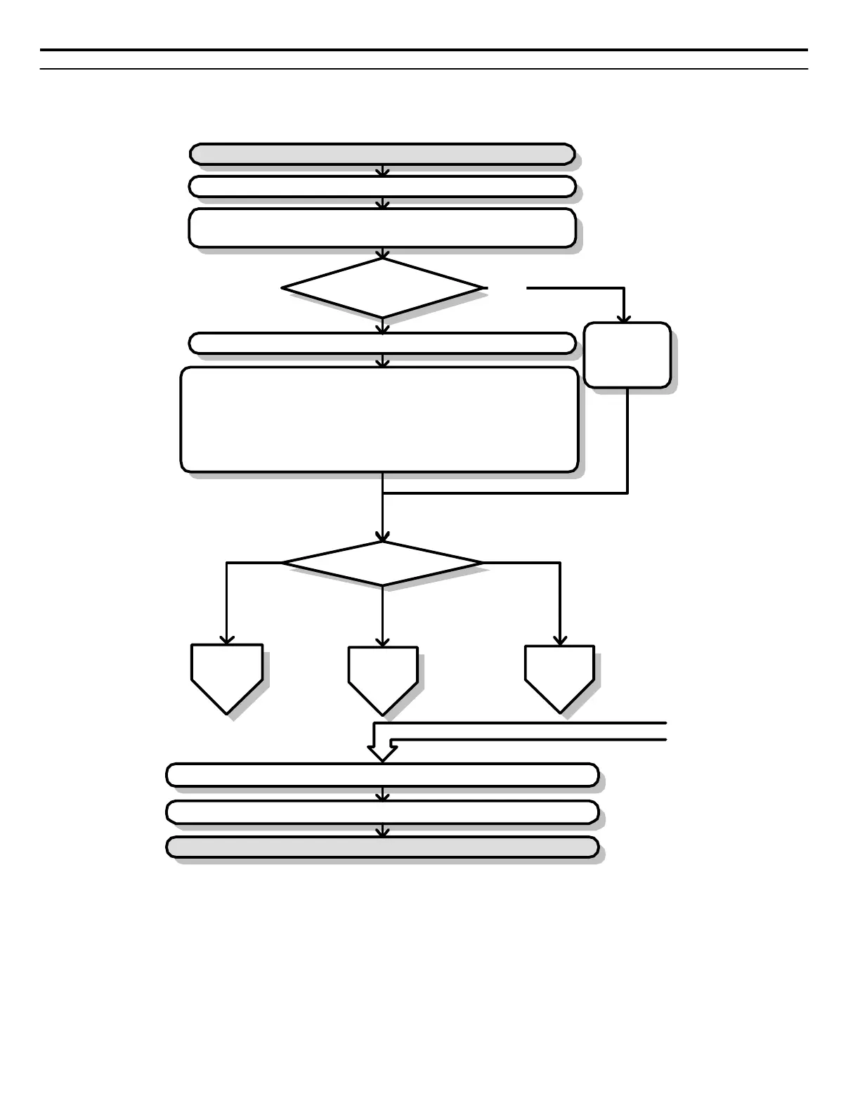
Flowchart A: Basic Start-Up and Motor Tuning
Flowchart A in Figure 4.8 describes a basic start-up sequence that varies slightly depending on the application. Use the drive
default parameter settings in simple applications that do not require high precision.
YES
NO
START
Install and wire he drive as explained in Chapters 1, 2, and 3
Apply main power on to the drive
Follow safety messages concerning applica ion of power
Application Presets
A1-06 used?
Set he control mode in parameter A1-02
Refer to
Application
Selec ion section
To
Flowchart A-1
Control Mode
A1-02 =
To
Flowchart A-2
To
Flowchart A-3
Set the basic parameters
b1-01/02 for frequency reference and run command source selection
H1-
oo,H2-oo,H3-oo,H4-oo,H6-oofor I/O terminal setting
d1-
oo for using multi-speed references
C1-
oo and C2-oofor accel/decel and S-curve time settings
C6-01 for heavy/normal duty mode selection
L8-55 = 0 if using a regen converter
L3-04 if using dynamic braking options
Fine tune parameters. Adjust application settings if necessary.
Check the machine operation and verify parameter settings.
Drive is ready to run the application.
From Flowchart A-1, A-2, or A-3
0: V/f
1: V/f w/PG
2: OLV
3: CLV
5: OLV/PM
6: AOLV/PM
7: CLV/PM
Figure 4.8 Basic Start-Up
Note: 1. Execute
Stationary Auto-Tuning for Line-to-Line Resistance if the drive has been Auto-Tuned and then moved to a different location where
the motor cable length exceeds 50 m.
2. Perform Auto-Tuning again after installing an AC reactor or other such components to the output side of the drive.
4.4 Start-Up Flowcharts
92
YASKAWA ELECTRIC SIEP C710616 31B YASKAWA AC Drive – A1000 Technical Manual

 Loading...


