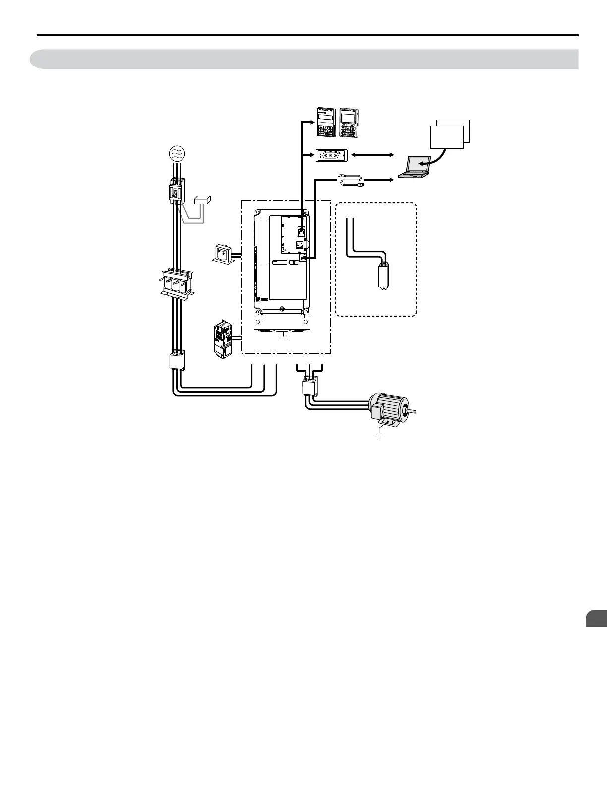
8.3 Connecting Peripheral Devices
Figure 8.1 illustrates how to configure the drive and motor to operate with various peripheral devices.
Refer to the specific manual for the devices shown below for more detailed installation instructions.
Copy
Verify
Read
LOCK
YASKAWA
JVOP-181
USB Copy Unit
COM ERR
PC
DriveWizard
Engineering Software Tools
DriveWorksEZ
Power
Supply
Line
Breaker
(MCCB)
or
Leakage
Breaker
Surge
Absorber
DC Reactor
AC Reactor
Input Side
Noise Filter
Braking Resistor
or Braking Resistor Unit
Output Side
Noise Filter
Drive
Ground
B1 B2
Motor
U/T1V/T2W/T3R/L1
24 V control
power supply
unit
S/L2
+2
+1
T/L3
Ground
USB Copy unit
USB Type-AB Cable
(sold separately)
LED Operator/LCD Operator
USB Cable
(Type-AB)
Figure 8.1 Connecting Peripheral Devices
Note: If the drive is set to trigger a fault output when the fault restart function is activated (L5-02 = 1), then a sequence to interrupt power when a
fault occurs will turn off the power to the drive while the drive attempts to restart. The default setting for L5-02 is 0 (fault output active during
restart).
8.3 Connecting Peripheral Devices
YASKAWA ELECTRIC SIEP C710616 31B YASKAWA AC Drive – A1000 Technical Manual
363
8
Peripheral Devices &
Options

 Loading...


