n
Installing Other Types of Braking Resistors
When installing braking resistors other than the ERF or LKEB types, make sure that the drive internal braking transistor will
not be overloaded with the required duty cycle and the selected resistance value. Use a resistor that is equipped with a thermal
overload relay contact, and utilize this contact to switch off the drive in case of braking resistor overheat.
n
Braking Resistor Overload Protection
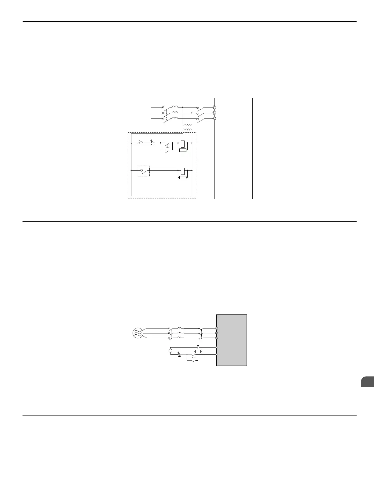
If using a braking resistor option, a sequence such as the one shown in Figure 8.7 should be set up to interrupt the power
supply in case the braking resistor overheats.
Drive
MC
Circuit Breaker
R
S
T
R/L1
S/L2
T/L3
SA
SA
575 V
MCON
MC
OFF
THRX
THRX
Braking Resistor Unit
(Close: Overheat)
1 2
Figure 8.7 Power Supply Interrupt for Overheat Protection (Example)
u
Installing a Molded Case Circuit Breaker (MCCB) and Earth Leakage Circuit Breaker
(ELCB)
Install an MCCB or ELCB for line protection between the power supply and the main circuit power supply input terminals R/
L1, S/L2, and T/L3. This protects the main circuit and devices wired to the main circuit while also providing overload
protection.
Consider the following when selecting and installing an MCCB or ELCB:
• The capacity of the MCCB or ELCB should be 1.5 to 2 times the rated output current of the drive. Use an MCCB or ELCB
to keep the drive from faulting out instead of using overheat protection (150% for one minute at the rated output current).
• If several drives are connected to one MCCB or ELCB that is shared with other equipment, use a sequence that shuts the
power OFF when errors are output by using magnetic contactor (MC) as shown in Figure 8.8.
R/L1
MB
MCCB
A
B
MC
MC
MC
MC
S/L2
T/L3
C
SA
A – Power supply
B – Drive
C – Control power supply
Figure 8.8 Power Supply Interrupt Wiring (Example)
WARNING! Electrical Shock Hazard. Disconnect the MCCB and MC before wiring terminals. Failure to comply may result in serious injury
or death.
u
Installing a Ground Fault Circuit Interrupter (GFCI)
Drive outputs generate high-frequency leakage current as a result of high-speed switching. Install a GFCI on the input side of
the drive to switch off potentially harmful leakage current.
Factors in determining leakage current:
8.5 Installing Peripheral Devices
YASKAWA ELECTRIC SIEP C710616 31B YASKAWA AC Drive – A1000 Technical Manual
367
8
Peripheral Devices &
Options

 Loading...


