u
L7: Torque Limit
OLV/PMOLV/PM AOLV/PMAOLV/PM CLV/PMCLV/PM
PM motor control modes are not available on 600 V class drives, CIMR-Ao5oooooooo.
No.
(Addr.
Hex)
Name Description Values Page
L7-01
(4A7)
Forward Torque Limit
V/f
OLV/PM
V/f w PG
AOLV/PM
OLV
CLV/PM
CLV
OLV/PM AOLV/PM
OLV
CLV/PM
CLVV/f
OLV/PM
V/f w PG
AOLV/PM
OLV
CLV/PM
CLV
OLV/PM AOLV/PM
OLV
CLV/PM
CLV
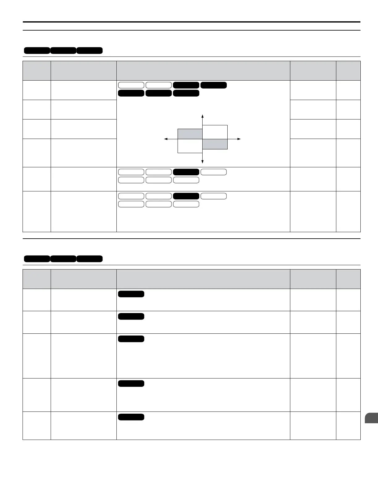
Sets the torque limit value as a percentage of the motor rated torque. Four
individual quadrants can be set.
L7-01
L7-03
L7-02
L7-04
Output Torque
Positive Torque
REV
Negative Torque
FWD
Motor
r/min
Regeneration
Regeneration
Default: 200%
Min.: 0
Max.: 300
262
L7-02
(4A8)
Reverse Torque Limit
Default: 200%
Min.: 0
Max.: 300
262
L7-03
(4A9)
Forward Regenerative
Torque Limit
Default: 200%
Min.: 0
Max.: 300
262
L7-04
(4AA)
Reverse Regenerative
Torque Limit
Default: 200%
Min.: 0
Max.: 300
262
L7-06
(4AC)
Torque Limit Integral Time
Constant
V/f
OLV/PM
V/f w PG
AOLV/PM
OLV
CLV/PM
CLVOLV
Sets the integral time constant for the torque limit.
Default: 200 ms
Min: 5
Max: 10000
262
L7-07
(4C9)
Torque Limit Control
Method Selection during
Accel/Decel
V/f
OLV/PM
V/f w PG
AOLV/PM
OLV
CLV/PM
CLVOLV
0: Proportional control (changes to integral control at constant speed). Use this
setting when acceleration to the desired speed should take precedence over the
torque limit.
1: Integral control. Set L7-07 to 1 if the torque limit should take precedence.
Default: 0
Range: 0, 1
262
u
L8: Drive Protection
OLV/PMOLV/PM AOLV/PMAOLV/PM CLV/PMCLV/PM
PM motor control modes are not available on 600 V class drives, CIMR-Ao5oooooooo.
No.
(Addr.
Hex)
Name Description Values Page
L8-01
(4AD)
Internal Dynamic Braking
Resistor Protection
Selection (ERF type)
All Modes
0: Resistor overheat protection disabled
1: Resistor overheat protection enabled
Default: 0
Range: 0, 1
263
L8-02
(4AE)
Overheat Alarm Level
All Modes
An overheat alarm will occur if the heatsink temperature exceeds the level set
in L8-02.
Default:
<1>
Min.: 50 °C
Max.: 130 °C
263
L8-03
(4AF)
Overheat Pre-Alarm
Operation Selection
All Modes
0: Ramp to stop. A fault is triggered.
1: Coast to stop. A fault is triggered.
2: Fast Stop. Decelerate to stop using the deceleration time in C1-09. A fault
is triggered.
3: Continue operation. An alarm is triggered.
4: Continue operation at reduced speed as set in L8-19.
Default: 3
Range: 0 to 4
263
L8-05
(4B1)
Input Phase Loss Protection
Selection
All Modes
Selects the detection of input current phase loss, power supply voltage
imbalance, or main circuit electrolytic capacitor deterioration.
0: Disabled
1: Enabled
Default: 1
Range: 0, 1
264
L8-07
(4B3)
Output Phase Loss
Protection Selection
All Modes
0: Disabled
1: Enabled (triggered by a single phase loss)
2: Enabled (triggered when two phases are lost)
Default: 1
Range: 0 to 2
264
B.10 L: Protection Function
YASKAWA ELECTRIC SIEP C710616 31B YASKAWA AC Drive – A1000 Technical Manual
433
B
Parameter List

 Loading...


